
Device and method for laser interferometry of inner cone angle

A technology of laser interference and measurement device, applied in the field of laser measurement, can solve the problems of easily damaged cone surface, poor universality of measurement ball, difficult measurement, etc., and achieves the effect of meeting measurement requirements and reducing measurement man-hours

Active Publication Date: 2018-08-14
CHANGCHUN UNIV OF SCI & TECH
View PDF4 Cites 0 Cited by
  • Summary
  • Abstract
  • Description
  • Claims
  • Application Information

AI Technical Summary

Problems solved by technology

[0004] Yet, there is following shortcoming in described two-ball measurement method: one, this method belongs to contact measurement, easily damages cone surface, as causes scratch, when cone surface is optical mirror surface, this damage is not allowed; Its two, This method requires the use of two measuring balls with a predetermined diameter. If the cone is shallow, the apex of the measuring ball is higher than the end face of the cone after the measuring ball is placed in the cone, and the measurement cannot be realized. Furthermore, the universality of the measuring ball is poor , if the scale range of the inner cone device to be tested is to be expanded, this method needs to prepare more measuring balls; third, the requirements for the inner cone device to be tested are more stringent, if the top of the cone is not a regular plane, the measurement difficulty will increase, Also introduces additional measurement error

Method used


Image

  • Device and method for laser interferometry of inner cone angle
  • Device and method for laser interferometry of inner cone angle
  • Device and method for laser interferometry of inner cone angle

Examples


Embodiment Construction

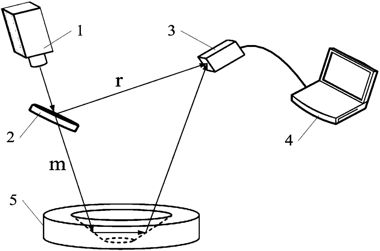
[0012] In the laser interferometry device of the inner cone angle of the present invention, such as figure 2 As shown, the laser 1 and the beam splitter 2 are arranged on the same optical axis, and the angle between the beam splitter 2 and the optical axis is 45°. The output wavelength λ of laser 1 is 532nm. The incident reflection mirror surface of the beam splitter 2 is coated with a film system whose transmittance of the output wavelength λ of the laser 1 is 50%, and the transmission mirror surface of the beam splitter 2 is coated with a film system whose transmittance of the output wavelength λ of the laser 1 is greater than 99.5%. The microscope CCD 3 is located on the reflection optical axis of the beam splitter 2, and the microscope CCD 3 is connected to the computer 4. The included angle θ between the reflected optical axis of the beam splitter 2 and the photosensitive surface s of the microscope CCD 3 is set to 76.98°. At this time, the maximum measurement range of ...


PUM


Abstract

A female cone angle laser interference measuring device and method are disclosed and belongs to the technical field of laser measurement. A contact measurement mode is currently available based on technologies of the prior art, and a work piece being tested can be damaged. In the measuring device disclosed in the invention, a laser device and a spectroscope are arranged on the same optical axis, the spectroscope and the optical axis form an included angle of 45 degrees, a microscope CCD is positioned on a reflection optical axis of the spectroscope, and the microscope CCD is connected with a computer; the measuring method disclosed in the invention is characterized in that a laser beam emitted by the laser device is split into a measuring light and a reference light via the spectroscope; a plane determined via intersection of an optical axis of the measuring light and an optical axis of the reference light overlaps with any meridian plane of a conical surface of a female cone device to be measured, the measuring light intersects with the reference light after being reflected twice, a position of a microscope CCD photosurface is adjusted along the optical axis of the reference light to a position where the measuring light intersects with the reference light, the microscope CCD sends an interference fringe image which is generated after the measuring light intersects with the reference light to the computer, an interference fringe interval is obtained after analyzing operation is conducted via the computer, and a female cone angle is calculated according to a formula shown in the description.

Description

technical field [0001] The invention relates to a laser interferometric measurement device and method for an inner cone angle, which uses laser interference technology to directly measure the inner cone angle with high precision and non-contact, and belongs to the technical field of laser measurement. Background technique [0002] Devices with inner conical surfaces are commonly used in high-precision machine tools, optical precision instruments, lasers, beam shaping and other fields. The existence of the inner cone angle error will directly affect the matching accuracy and service life of the device. Among them, the error of the inner cone angle is an important evaluation criterion for such parts or components. Existing methods for measuring the inner cone angle include direct measurement and indirect measurement, the former such as the three-coordinate detection method, and the latter such as the double-sphere measurement method. "The method of measuring the inner cone an...

Claims


Application Information

Patent Timeline
Patent Type & Authority Patents(China)
IPC IPC(8): G01B11/26
CPCG01B11/26
Inventor 董渊金光勇李青松李述涛于永吉王超张喜和
Owner CHANGCHUN UNIV OF SCI & TECH
Learn More