Liquid-level detection device for granular sludge storage tank of anaerobic system

A granular sludge and liquid level detection technology, which is applied in the direction of buoy liquid level indicators, etc., to achieve the effects of low manufacturing cost, highly intuitive and obvious, and energy saving

Pending Publication Date: 2016-12-07
无锡践行中欧科技有限公司
View PDF5 Cites 0 Cited by
  • Summary
  • Abstract
  • Description
  • Claims
  • Application Information

AI Technical Summary

Problems solved by technology

At present, anaerobic biological treatment technologies mainly include UASB, IC, EGSB and other anaerobic treatment technologies, but these anaerobic technologies all have the problem of storage and timely sales of production by-products (granular sludge)

Method used


Image

  • Liquid-level detection device for granular sludge storage tank of anaerobic system

Examples


Embodiment Construction

[0010] The specific embodiments of the present invention will be further described below in conjunction with the accompanying drawings.

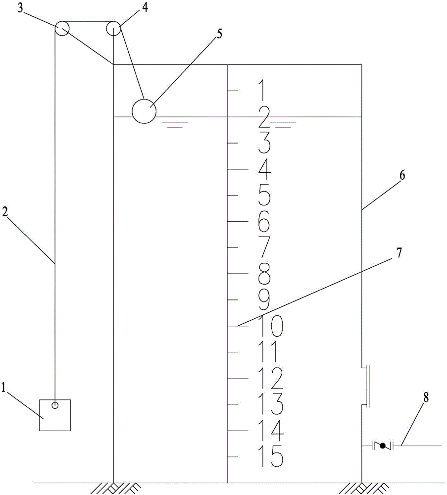
[0011] figure 1 Among them, including weight 1, pull rope 2, first fixed pulley 3, second fixed pulley 4, floating ball 5, granular sludge tank 6, scale 7, mud inlet pipe 8, etc.

[0012] Such as figure 1 As shown, the present invention is a liquid level detection device for a granular sludge storage tank, comprising a granular sludge tank 6, the outer surface of the granular sludge tank 6 is provided with a scale 7 arranged in a vertical direction, and the granular sludge tank 6 The first fixed pulley 3 and the second fixed pulley 4 are rotated on the top bracket, and the stay rope 2 is arranged on the first fixed pulley 3 and the second fixed pulley 4, and the stay rope 2 is placed on the outer part of the granular sludge tank 6 The lower end is connected to the weight 1, and the pull rope 2 is placed on the inner part of the granular sl...


PUM


Abstract

The invention relates to a high-efficiency anaerobic system, in particular to a liquid-level detection device for a granular sludge storage tank. The liquid-level detection device comprises a granular sludge tank, a scale is arranged on the outer surface of the granular sludge tank in the vertical direction, a first fixed pulley and a second fixed pulley are rotationally arranged on a top support of the granular sludge tank, a pull rope is arranged on the first fixed pulley and the second fixed pulley, and placed at the lower end of the outer side of the granular sludge tank to be connected with a heavy hammer, and placed at the lower end of the inner side of the granular sludge tank to be connected with a floating ball, and the floating ball floats on the liquid surface inside the granular sludge tank. The liquid-level detection device disclosed by the invention is visualized and obvious in tank liquid-level height, and does not require a power supply to save energy, has long service life, low production cost and no need to purchase a hydrostatic level gauge, lowers project operation risks and avoids methane explosion caused by electric leakage.

Description

technical field [0001] The invention relates to a high-efficiency anaerobic system, in particular to a liquid level detection device for a granular sludge storage tank of an anaerobic system. Background technique [0002] With the rapid development of industry and agriculture in our country and the improvement of urbanization level, the high-concentration organic wastewater discharged into the environment continues to increase, causing very serious pollution to the environment and severely destroying available water resources. The task of water treatment is imminent. At present, water pollution control methods mainly include physical treatment, chemical treatment, anaerobic biological treatment, aerobic biological treatment and advanced oxidation treatment technologies. Among them, the effect of physical treatment is not obvious, and has no obvious effect on the degradation of organic matter; chemical and advanced oxidation treatment technologies have the risk of secondary ...

Claims


Application Information

Patent Timeline
Patent Type & Authority Applications(China)
IPC IPC(8): G01F23/42
CPCG01F23/42
Inventor 赵旭东
Owner 无锡践行中欧科技有限公司
Why Eureka
Try Eureka