High Speed ​​Ejection Model Quick Release

A release device and model technology, applied in the field of aerospace engineering, can solve the problems of single launching attitude, short action time, and increased piston movement resistance, etc., and achieve the effects of improving the test success rate, improving the release effect, and increasing the rotational torque.

Active Publication Date: 2018-09-14
CHINA ACAD OF AEROSPACE AERODYNAMICS
View PDF6 Cites 0 Cited by
  • Summary
  • Abstract
  • Description
  • Claims
  • Application Information

AI Technical Summary

Problems solved by technology

The design of the original mechanism does not conform to the scientific principles. At the same time, there are problems such as short action time and insufficient inertia moment. As a result, the launching claws of the original launching mechanism collide with the model very easily, causing the test to fail.
This has become a difficult problem that the original institution cannot overcome, and the test institution must improve
[0006] 2) Rigid impacts lead to deformation of parts and poor mechanism stability
Every time the model of the original mechanism is launched, the steel piston will rigidly collide with the front pad of the copper cylinder to achieve the purpose of deceleration. Interference occurs, the piston movement resistance becomes larger, or even stuck, which leads to poor stability of the mechanism, lower model launch efficiency, and extremely inconvenient use, which needs to be improved
[0007] 3) The launch attitude of the model is single, which cannot meet the task requirements of more models
The original mechanism can only eject the model forward according to a fixed attitude angle, and more and more model tasks require the model not only to have a certain initial angle but also to have a certain angular velocity during the free flight process, while the original mechanism Cannot meet this goal, needs improvement
[0008] 4) The repeatability of the launch speed of the model is not high, which affects the test results, and the piston rod of the main cylinder will appear to have insufficient stamina even under the condition of high air source pressure. The original mechanism needs to be improved

Method used


Image

  • High Speed ​​Ejection Model Quick Release
  • High Speed ​​Ejection Model Quick Release
  • High Speed ​​Ejection Model Quick Release

Examples


Embodiment Construction

[0057] The present invention will be further described in detail below in conjunction with the accompanying drawings, so that those skilled in the art can implement it with reference to the description.

[0058] It should be understood that terms such as "having", "comprising" and "including" as used herein do not entail the presence or addition of one or more other elements or combinations thereof.

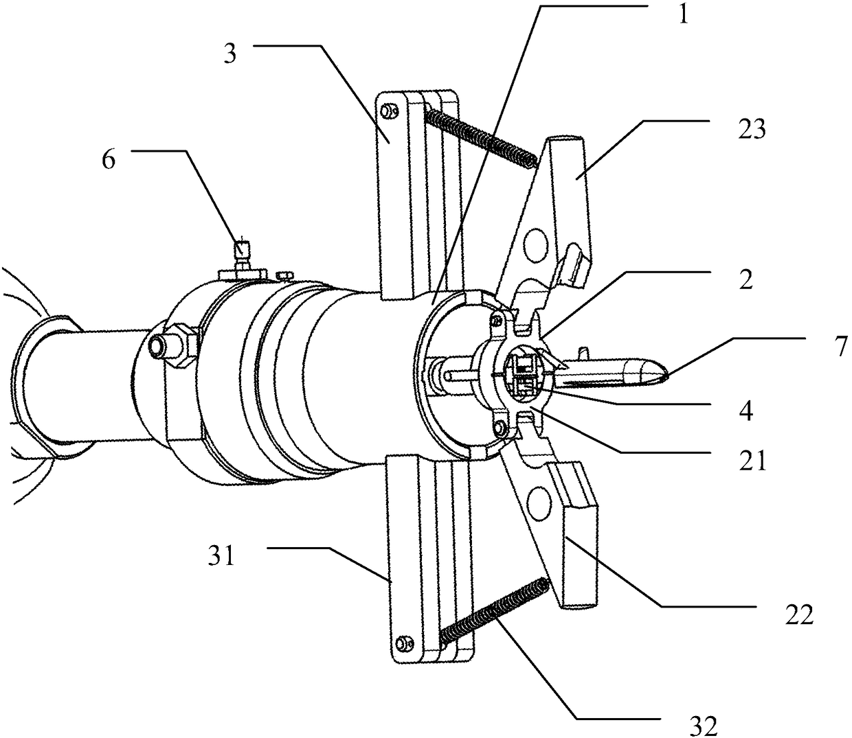
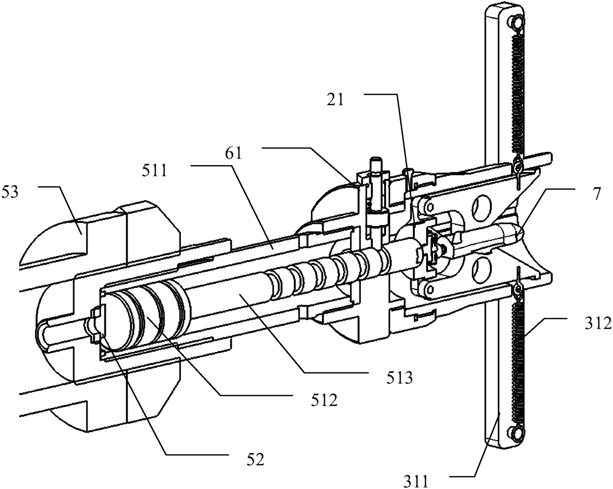
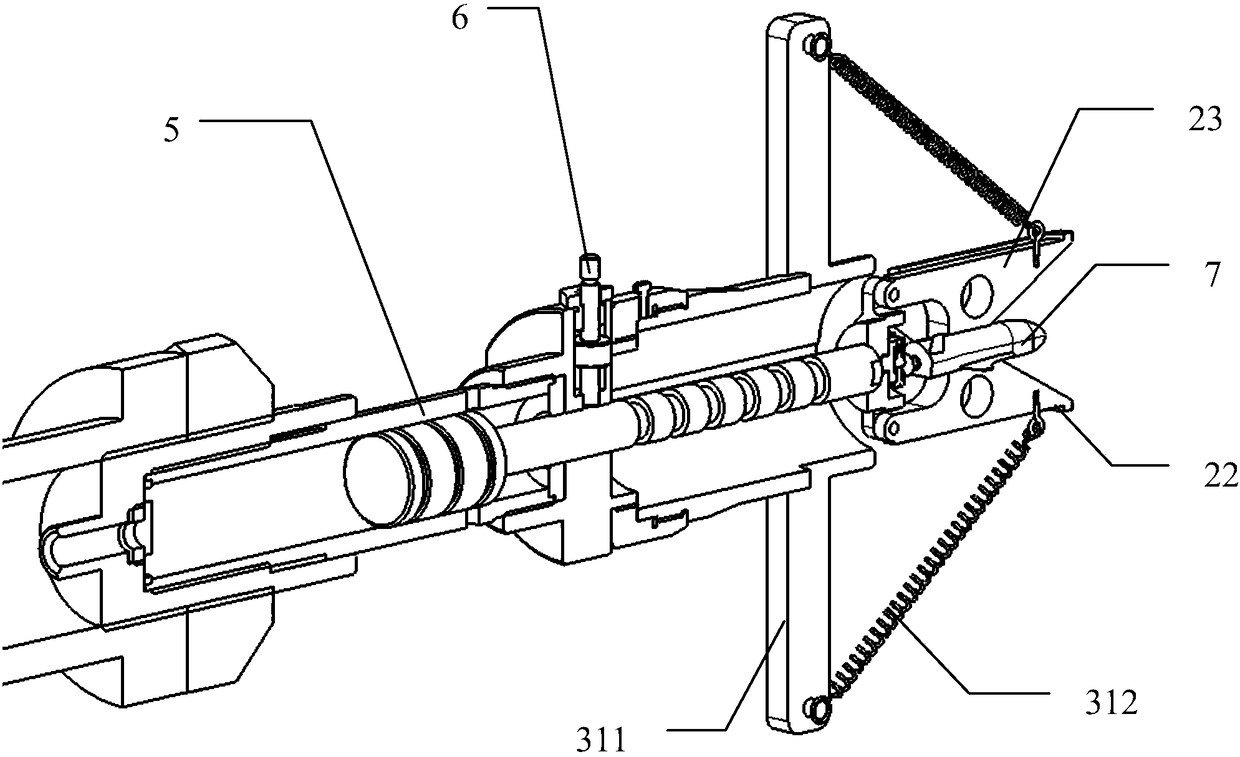
[0059] like Figure 1~4 As shown, the present invention provides a quick release device for a high-speed ejection model, including: a launching cylinder 1 , a launching mechanism 2 , an opening mechanism 3 and a driving mechanism 5 .

[0060] The launch tube 1 is approximately cylindrical and hollow inside. The launch mechanism 2 is movably arranged in the launch tube 1, and the launch mechanism 2 is used to eject the ejection model 7; the launch mechanism 2 includes: a fixed ring 21 and at least two launch claws 22 and 23, taking the launch claw 22 as an example, the launch cla...


PUM


Abstract

The invention discloses a high speed ejector model quick release device, including a launching cylinder, a launching mechanism, an opening mechanism and a drive mechanism. The launching mechanism includes a fixing ring and at least two launching claws. Rear ends of the launching claws are pivoted on the outer peripheral wall of the fixing ring. The opening mechanism comprises opening devices of the same number as that of the launching claws. Each opening device includes a strut and an opening spring. One end of each strut is fixed on the outer surface of the launch cylinder. One end of each opening spring is connected with one end of the corresponding strut, and the other end is connected to the front portions of the launching claws. The drive mechanism is connected with the fixing ring and drives the fixing ring to move from an opening at the front portion of the launching cylinder to the outside of the launching cylinder. The invention not only avoids the collision problem between a high speed ejection model and the launching mechanism, eliminates the deformation caused by the rigid collision between parts and improves the stability of a launching system, but also realizes the adjustment of the pitch and yaw rates of the ejector model and improves the reliability of a test mechanism, so that the model launch has a high repeatability.

Description

technical field [0001] The invention relates to the support and launch of a wind tunnel test model, in particular to a quick release device for a high-speed ejection model, which belongs to the field of aerospace engineering. Background technique [0002] Model free-flying wind tunnel test technology is a commonly used research method to study the dynamic aerodynamic characteristics of aircraft, and this type of technology has served model missions many times. The basic method of the test is to fix the free-flying model on the launching mechanism of the scimitar in the sub-span supersonic or hypersonic wind tunnel. After the flow field is stable, the model is ejected at high speed against the direction of the airflow. The model will fly in a short time. Free flight in the wind tunnel. At this time, high-speed photography is used to shoot the model through the observation window, and the attitude track of the free flight of the aircraft model can be obtained. After data proce...

Claims


Application Information

Patent Timeline
Patent Type & Authority Patents(China)
IPC IPC(8): G01M9/02G01M9/08
CPCG01M9/02G01M9/08
Inventor 薛飞杨益农朱剑
Owner CHINA ACAD OF AEROSPACE AERODYNAMICS
Why Eureka
Try Eureka