Distributed MIMO radar target tracking accuracy joint resource optimization method

A radar target tracking and resource optimization technology, applied in the field of distributed MIMO radar target tracking accuracy joint resource optimization, can solve the problem that the target position cannot be obtained in advance

Active Publication Date: 2016-12-07
THE PLA INFORMATION ENG UNIV
View PDF4 Cites 35 Cited by
  • Summary
  • Abstract
  • Description
  • Claims
  • Application Information

AI Technical Summary

Problems solved by technology

However, in practical applications, the target position cannot be obtained in advance

Method used


Image

  • Distributed MIMO radar target tracking accuracy joint resource optimization method
  • Distributed MIMO radar target tracking accuracy joint resource optimization method
  • Distributed MIMO radar target tracking accuracy joint resource optimization method

Examples


Embodiment 1

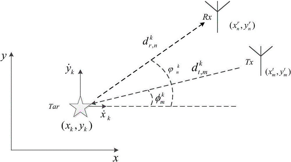
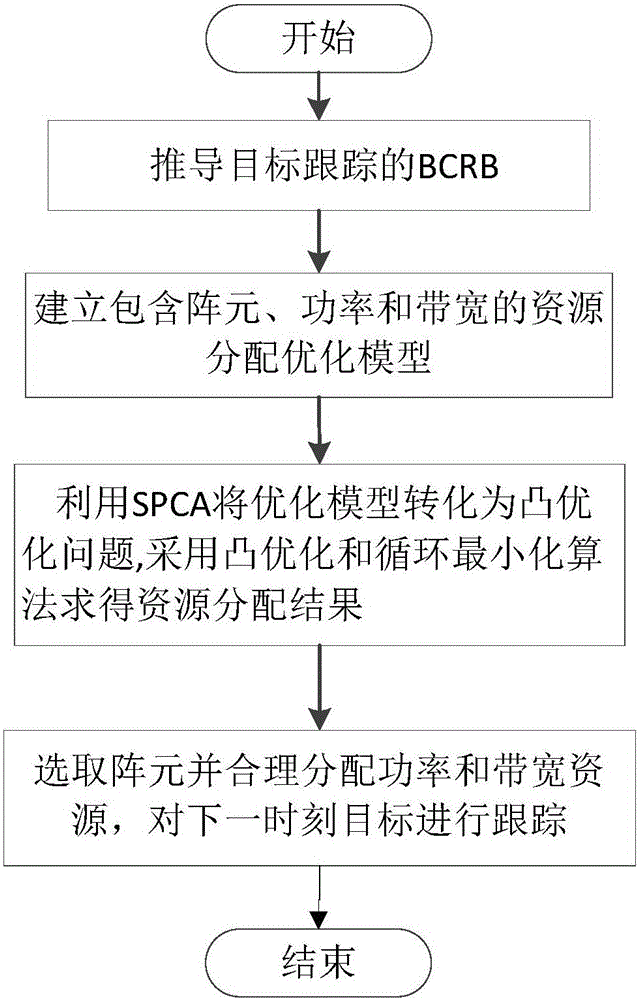
[0088] Embodiment one, see Figure 1~2 As shown, a distributed MIMO radar target tracking accuracy joint resource optimization method includes the following steps:

[0089] Step 1, deriving the Bayesian Cramerot bound BCRB of the moving target position, and determining the objective function;

[0090] Step 2. By minimizing the objective function, a resource allocation optimization model including three variables of array element, power and bandwidth is established;

[0091] Step 3, using the SPCA method to transform the resource allocation optimization model into a convex optimization problem, and solve it through the convex optimization method and the circular minimization method, and obtain the selected array element and the final power allocation result, as well as the optimal bandwidth allocation vector;

[0092]Step 4. Estimate and track the target position at the next moment according to the selected array element, the final power allocation result and the optimal bandw...

Embodiment 2

[0094] Embodiment two, see Figure 1-8 As shown, a distributed MIMO radar target tracking accuracy joint resource optimization method includes the following content:

[0095] (1) Determination of the objective function

[0096] Use the observed vector r to estimate an unknown vector to be estimated Its BCRB can be expressed as:

[0097]

[0098] where J B Indicates Bayesian information matrix (BIM, Bayesian information matrix), C B represents the BCRB matrix, J B Can be expressed as a linear superposition of two matrices:

[0099]

[0100] Among them, J D (x k ) = E xk [J r (x k )], representing the joint probability density function with respect to the target state vector x k expectations, and J r (x k ) means that the BCRB is related to the system observations at time k, and can be obtained by the chain rule:

[0101]

[0102] Among them, the Jacobian matrix Represents the partial derivative with respect to the target state vector, given by the ta...


PUM


Abstract

The invention relates to a distributed MIMO radar target tracking accuracy joint resource optimization method. The method includes the following steps that: an objective function is derived, a resource allocation optimization model containing three variables, namely, array element, power and bandwidth is constructed; the model is simplified, an array element selection problem is converted into a convex optimization problem from a 0-1 problem through convex relaxation; and the optimization model is decomposed into iterative optimization sub-problems of array element selection and power allocation through using cyclic minimization, the problems are solved through using an SPCA (sequential parametric convex approximation) method until the objective function is not optimized any more, final array element selection and power allocation results are obtained, and a final bandwidth allocation result is calculated, and a target position at a next time point is estimated. According to the distributed MIMO radar target tracking accuracy joint resource optimization method of the invention, the accuracy of the target tracking of an MIMO radar can be effectively improved through resource allocation, and the utilization rate of resources can be also improved; and an appropriate array element subset is selected, and power and bandwidth resources are allocated optimally, and therefore, the accuracy of the target tracking can be further improved under a situation that radar system resources are limited.

Description

technical field [0001] The invention belongs to the technical field of radar target tracking, in particular to a distributed MIMO radar target tracking accuracy joint resource optimization method. Background technique [0002] MIMO radar is a radar system that uses multiple transmitting array elements to send customized waveform signals, and uses multiple receiving array elements to jointly process the echo. It has become a hot spot in the research of new system radars. In general, MIMO radars can be divided into two categories: centralized MIMO radars and distributed MIMO radars. Centralized MIMO radar mainly uses its waveform diversity and flexible waveform design method to improve the estimation performance of target parameters; while distributed MIMO radar mainly uses the space diversity gain of target RCS to improve system performance. MIMO radar is a radar monitoring system, and target tracking is a core task for it. The present invention selects distributed MIMO rada...

Claims


Application Information

Patent Timeline
Patent Type & Authority Applications(China)
IPC IPC(8): G01S13/66
CPCG01S13/66
Inventor 郑娜娥孙扬任修坤陈松吕品品赵峰赵远李玉翔高留洋
Owner THE PLA INFORMATION ENG UNIV
Why Eureka
Try Eureka