Optical brightness enhancement film and manufacturing method thereof

A brightness-enhancing film and optical technology, which is applied in the field of optics, can solve problems such as light interference and easy scratching of the brightness-enhancing film, and achieve the effects of improving covering performance, facilitating operation, and saving production costs

Pending Publication Date: 2016-12-07
NINGBO EXCITON TECH
View PDF10 Cites 10 Cited by
  • Summary
  • Abstract
  • Description
  • Claims
  • Application Information

AI Technical Summary

Problems solved by technology

[0006] In order to solve the problems that the existing brightness enhancement film is easy to scratch and

Method used


Image

  • Optical brightness enhancement film and manufacturing method thereof
  • Optical brightness enhancement film and manufacturing method thereof
  • Optical brightness enhancement film and manufacturing method thereof

Examples


Embodiment 1

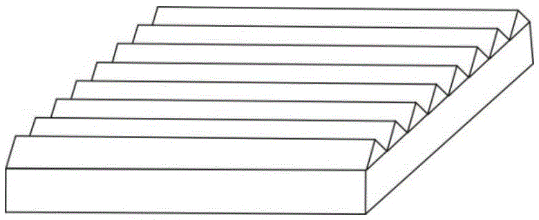
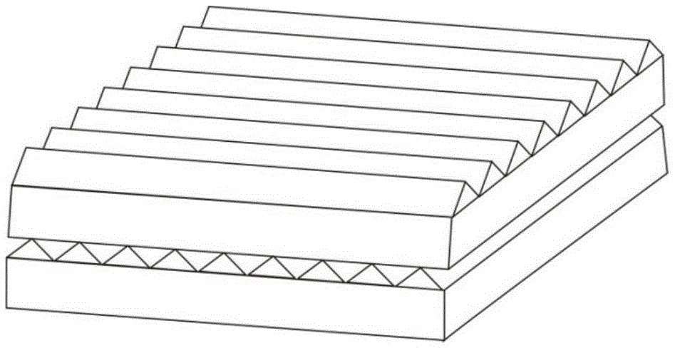
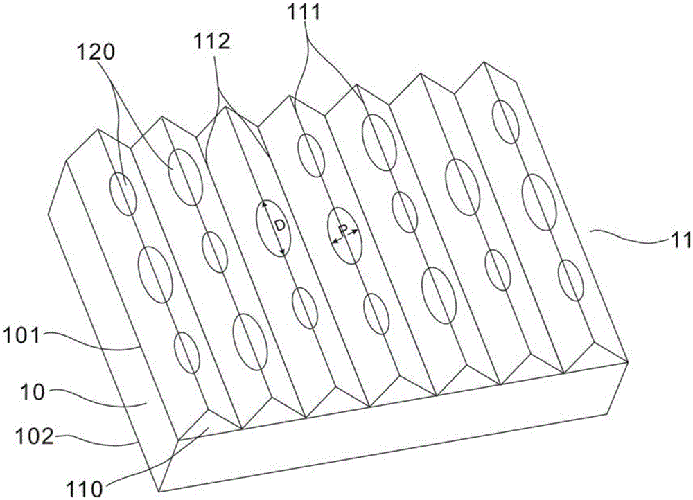
[0065] The present invention provides an optical brightness enhancement film. The brightness enhancement film comprises a substrate layer 10 and a light concentrating microprism structure layer (microprism layer for short) 11, and the light concentrating microprism structure layer 11 is bonded to the substrate. On the surface of the material layer 10, the light concentrating microprism structure layer 11 includes several microprism columns 110;

[0066] The microprism column 110 has a higher peak line 111, and two valley lines 112 positioned on the left and right sides of the peak line 111 and lower in height, and the valley lines 112 of adjacent microprism columns 110 overlap each other; The angle at which the peak line 111 of the microprism column is called the microprism peak angle (also known as the microprism vertex angle);

[0067] An arc-shaped raised structure 120 is arranged on the peak angle of the microprism, and the arc-shaped raised structure 120 is symmetrical ab...

Embodiment 2

[0078] The optical brightness enhancement film provided in Example 1, wherein,

[0079] The material of the substrate layer is polyethylene terephthalate (PET).

[0080] The thickness of the substrate layer 10 is 600 μm.

[0081] The material of the light concentrating microprism structure layer 11 is ultraviolet curable polyurethane acrylate resin.

[0082] The peak angle is 160 degrees; the height H of the microprism column 110 is 50 μm.

[0083] The transverse width of the arc-shaped raised structure 120 is P, 30 μm≤P≤40 μm; the length of the arc-shaped raised structure 120 parallel to the length of the microprism column 110 is the longitudinal length, and the longitudinal length is D, 250 μm≤D≤ 300 μm.

[0084] The height from the peak line 111 of the microprism column 110 to the highest point of the arc-shaped convex structure 120 is H°, 15 μm≤H°≤20 μm.

[0085] The distance between adjacent lowest points of the adjacent arc-shaped convex structures 120 is L, and 4800...

Embodiment 3

[0087] The optical brightness enhancement film provided in Example 1, wherein,

[0088] The material of the substrate layer is polycarbonate (PC).

[0089] The thickness of the substrate layer 10 is 300 μm.

[0090] The material of the light concentrating microprism structure layer 11 is ultraviolet curable polyurethane acrylate resin.

[0091] The peak angle is 100 degrees; the height H of the microprism column 110 is 25 μm.

[0092] The transverse width of the arc-shaped protrusion structure 120 is P, 10 μm≤P≤15 μm; the longitudinal length of the arc-shaped protrusion structure 120 is D, 120 μm≤D≤150 μm.

[0093] The height from the peak line 111 of the microprism column 110 to the highest point of the arc-shaped convex structure 120 is H°, 8 μm≤H°≤10 μm.

[0094] The distance between adjacent lowest points of the adjacent arc-shaped convex structures 120 is L, 2200 μm≤L≤2500 μm.


PUM

PropertyMeasurementUnit
Heightaaaaaaaaaa
Horizontal widthaaaaaaaaaa
Longitudinal lengthaaaaaaaaaa

Abstract

The invention relates to the technical field of optics, and particularly relates to an optical brightness enhancement film applied to a liquid crystal display, so as to solve the problems that the existing brightness enhancement film is likely to scratch and optical interference is likely to happen. The optical brightness enhancement film provided by the invention comprises a substrate layer and a light-gathering microprism structure layer, wherein the light-gathering microprism structure layer is bonded on the surface of the substrate layer; the light-gathering microprism structure layer comprises a plurality of microprism columns; each microprism column is provided with a crest line with a high height and two valley lines located at the left side and the right side of the crest line and low heights, and the valley lines of adjacent microprism columns are mutually overlapped; the angle of the crest line of the microprism column is called a microprism crest angle; the microprism crest angle is provided with arc-shaped convex structures symmetric relative to the microprism crest angle; and the surface profile in the cross section of the arc-shaped convex structure is arc-shaped. The optical brightness enhancement film of the invention has the anti-scratching performance and interference reduction performance, and also, high brightness and a wide viewing angle are provided.

Description

technical field [0001] The invention relates to the field of optical technology, in particular to an optical brightness enhancement film applied to a liquid crystal display. Background technique [0002] Brightness Enhancement Film (BEF, Brightness Enhancement Film), also known as Brightness Enhancement Film or Prism Sheet, plays the role of converging the light emitted by the light source to increase the display brightness and save the energy of the display battery device. The principle of the Brightness Enhancement Film is to use A layer of microprism structure on its surface adjusts the light emitted outside the observer's viewing angle to within the viewing angle of the observer through refraction and reflection, so as to improve the brightness of the LCD and the utilization rate of the emitted light energy. Therefore, the brightness enhancement film is one of the most important optical films widely used in the backlight module of the liquid crystal display. [0003] Ex...

Claims


Application Information

Patent Timeline
IPC IPC(8): G02B5/02G02B5/04
CPCG02B5/045G02B5/0231
Inventor 余洋顾春红于振江李刚唐海江张彦
Owner NINGBO EXCITON TECH
Why Eureka
Try Eureka