Fare gate passing logic control system and method

A technology of logic control and ticket gate, applied in the general control system, control/regulation system, computer control, etc., can solve the problems of reducing traffic efficiency, impact of traffic efficiency, pedestrian slowness, etc., to reduce the length of traffic, avoid traffic delays, The effect of reducing security risks

Active Publication Date: 2016-12-07
浙江网新电气技术有限公司
View PDF11 Cites 35 Cited by
  • Summary
  • Abstract
  • Description
  • Claims
  • Application Information

AI Technical Summary

Problems solved by technology

[0006] After research, it is found that the existing ticket gates mainly have the following defects in the passage logic control: First, the time interval from opening to closing after each ticket inspection is fixed, so it is not optimized enough. Once it is successfully completed, the fixed duration of this time interval can only be set to exceed the actual passing time of normal pedestrians. Although the exceeding time is extremely short each time, it still brings a non-negligible impact to the passing efficiency. influences
Secondly, for a small number of situations that cannot complete the passage within the above time interval, such as pedestrians who are abnormally slow, carrying luggage, or pulling children, etc., the turnstiles will open and close repeatedly to avoid accidental clamping, or pedestrians have not yet passed. The barrier turnstile is already closed, which will reduce the traffic efficiency, and even need to be solved manually, resulting in the fact that the turnstile cannot pass effectively within a few minutes
Furthermore, the gates are equipped with an alarm function based on the premise of counting traffic for trailing and evading fares, but the false alarm rate is high. For example, normal behaviors such as dragging luggage or leading children through the gates may cause unnecessary alarms

Method used


Image

  • Fare gate passing logic control system and method
  • Fare gate passing logic control system and method
  • Fare gate passing logic control system and method

Examples


Embodiment Construction

[0033] The technical solutions of the present invention will be further specifically described below through examples.

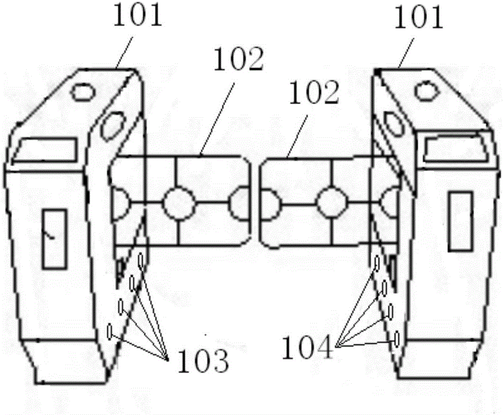
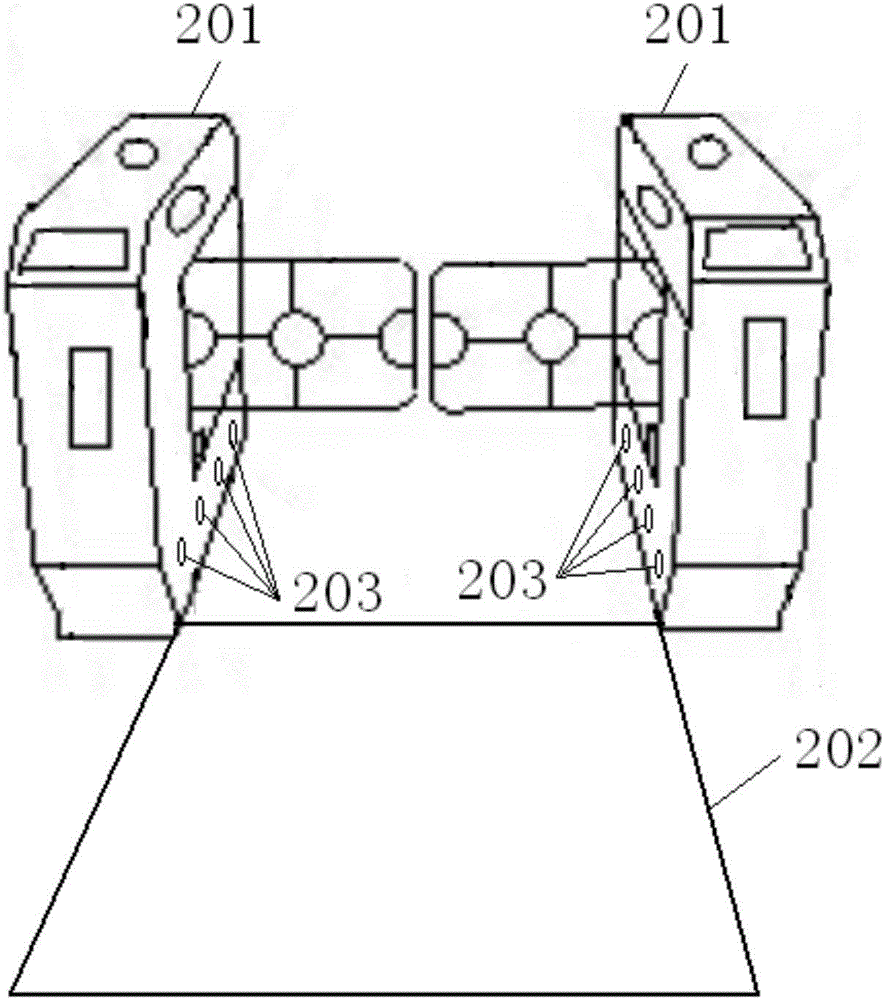
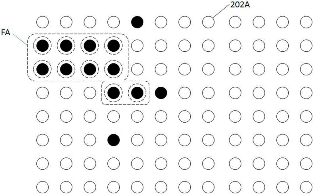
[0034] figure 2 It is a schematic diagram of the overall structure of the passage logic control system of the ticket gate according to the present invention. This system is on the outside of the passing space defined by the left and right gates of the ticket gate 201 (along the passing direction of pedestrians, the side that does not pass the gate is the outside, and the side that passes the gate is the inside), along the passageway. A traffic state detection area 202 is set in the direction; the traffic state detection area 202 detects the position signal of the pedestrian's landing area in the way of pressure sensing, and serves as the basis for judging the traffic mode, traffic step distance, and moving speed. An infrared light curtain 203 is installed on the gate of the ticket gate, including several groups of one-to-one corresponding infrared transmit...


PUM


Abstract

The invention provides a fare gate passing logic control system and method. According to the fare gate passing logic control system and method, a passing state detection area with pressure sensing as an implementation mode is arranged in a certain distance range in front of a gate passage, and the passing speed and the passing state of current pedestrians are predicted and calculated in combination of infrared light curtains installed on gate doors of a gate; a time interval from opening to closing of the gate is adaptively adjusted according to the passing speed and the passing state, the passing time duration is distributed as needed, and the average passing duration is shortened compared with passing logic control of a fixed time interval; for people moving slowly or carrying luggage or taking children or the like, the time interval from opening to closing of the gate is prolonged based on the predicted passing speed and passing state, so that on one hand, safety risk is reduced, and on the other hand, passing delay caused by repeated opening and closing of the gate or the advanced closing of the gate is avoided; through effective recognition of the passing state, mistaken alarming can be avoided, and recognized following gate breaking and other behaviors can be effectively warned.

Description

technical field [0001] The invention relates to the field of public passage facilities, in particular to a passage logic control system and method for ticket gates. Background technique [0002] Ticket gates are commonly used public traffic facilities in subway stations, park gates, theater entrances, gate entry and exit and other places. Such as figure 1 As shown, the fully automatic ticket gate generally has a gate 101 and a retractable and expandable arrester 102. When the gate is opened, the arrester is in a retracted state, and the gate is open, and pedestrians can pass through it; The device is unfolded to close the gate; the blocker is generally made of high-strength engineering plastics, plexiglass, metal and other materials. Compared with semi-automatic ticket gates using single-roller or three-roller barriers, this kind of fully automatic ticket gates has higher traffic efficiency, more convenient pedestrian passage, and better safety. [0003] In order to prote...

Claims


Application Information

Patent Timeline
Patent Type & Authority Applications(China)
IPC IPC(8): G05B19/048
CPCG05B19/048
Inventor 陈根土沈新锋钱红兴赵和平唐宗生
Owner 浙江网新电气技术有限公司
Why Eureka
Try Eureka