Improved beverage bottle recovering machine and beverage bottle recovering method thereof

A technology for recycling machines and beverage bottles, applied in the direction of starting with returnable containers, coinless or similar appliances, instruments, etc., can solve the problems of limited promotion and high cost, and achieve non-destructive, long service life, and improve environmental protection conscious effect

Inactive Publication Date: 2016-12-07
CHONGQING JIZHAN TECH DEV CO LTD
6 Cites 0 Cited by

AI-Extracted Technical Summary

Problems solved by technology

Beverage bottles with damaged outer packaging or dirt on the surface, and beverage bottles that are put in incorrectly by people at...

Abstract

The invention discloses an improved beverage bottle recovering machine and a beverage bottle recovering method thereof. The beverage bottle recovering machine comprises a base and a recovering machine body arranged on the base, a front door assembly is arranged outside the recovering machine body and comprises a front door body hinged to one side of the recovering machine body, the outer wall of the front door body is provided with a touch display screen and a feeding opening, the feeding opening is formed in the other side of the front door body, a display screen protective cover is arranged at the position, corresponding to the touch display screen, of the inner wall of the front door body, a controller protective cover is arranged at the lower end of the display screen protective cover, a controller where software for recovering beverage bottles in a paid mode is installed is arranged in the controller protective cover, and a feeding door assembly and a bottle checking device assembly which are capable of sliding up and down are arranged at the position, corresponding to the feeding opening, of the inner wall of front door body. The beverage bottle recovering machine is a paid recovering device and is long in service life, and all the components are not prone to damage; people can obtain deserved return from waste recycling just by putting the beverage bottles into the device, so that the enthusiasm of taking part in waste recycling of the public is enhanced, and environmental consciousness of people is improved.

Application Domain

Returnable containers actuation

Technology Topic

Image

  • Improved beverage bottle recovering machine and beverage bottle recovering method thereof
  • Improved beverage bottle recovering machine and beverage bottle recovering method thereof
  • Improved beverage bottle recovering machine and beverage bottle recovering method thereof

Examples

  • Experimental program(1)

Example Embodiment

[0019] The present invention will be further described below in conjunction with specific embodiments. The exemplary embodiments and descriptions of the present invention are used to explain the present invention, but not as a limitation to the present invention.
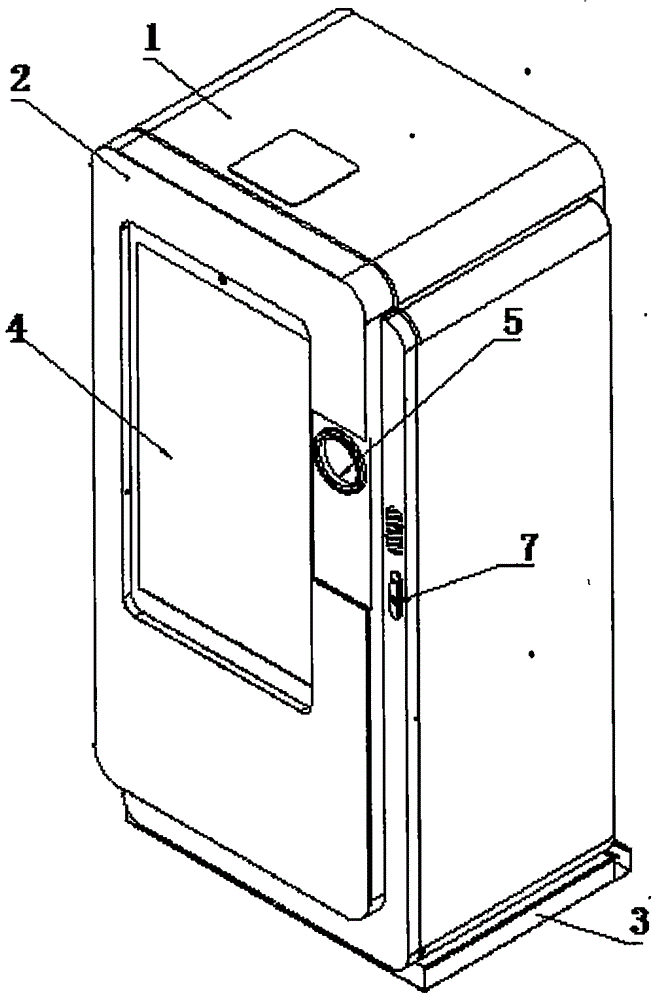
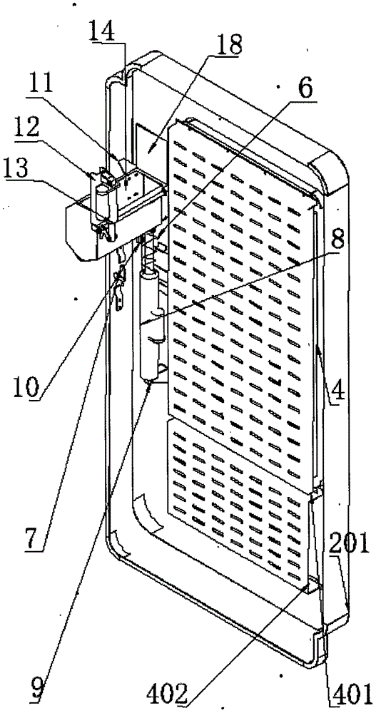
[0020] like figure 1 , figure 2 , image 3 , Figure 4 The improved beverage bottle recycling machine of the present invention shown includes a base 3, a recycling machine main body 1 arranged on the base 3, and a front door assembly 2 is provided outside the recycling machine main body 1, and the front door assembly 2 includes a The front door main body 201 hinged on one side of the main body 1 of the recycling machine, the outer wall of the front door main body 201 is provided with a touch display screen 4 and a feeding port 5, the feeding port 5 is arranged on the other side of the front door main body 201, and the inner wall of the front door main body 201 is provided with a corresponding touch display screen 4. Display screen shield 401, the lower end of display screen shield 401 is provided with controller shield 402, and controller shield 402 is provided with the controller (not shown in the figure) that the software of paid recovery beverage bottle is installed, front door main body 201 The inner wall is provided with a feeding door assembly and a bottle detector assembly that can slide up and down corresponding to the feeding port 5. The feeding door assembly includes a feeding door 18 and a first electric push rod 8. The feeding door 5 is installed on the inner wall of the front door body 201. In the chute 6 vertically arranged on the side, the bottom of the feeding door 18 is equipped with the feeding door strut lug 19, and the bottom of the first electric push rod 8 is vertically fixed on the inner wall of the front door main body 201 with the first electric push rod lug 9. The top of an electric push rod 8 is fixedly connected with the charging door strut ear 9, and the first electric push rod 8 is covered with a spring 6, and the top of the spring 6 is fixed to the feeding gate strut ear 9 of the feeding gate 18. connection, the lower end of the spring 6 is fixed in the middle of the first electric push rod 8; the bottle detector assembly includes a bottle detector connection seat 11, an inner code scanner 14, a second electric push rod 13 and a swing door assembly, and the bottle inspection The connector connecting seat 11 is fixed on the inner wall of the front door main body 201 corresponding to the feeding port 5, the inner code scanner 14 is fixed above the connecting seat 11 of the bottle detector, and the second electric push rod 13 is fixed on the front door main body 201 through the second electric push rod lug 12. On the side wall, the top of the second electric push rod 13 is connected to the swing door assembly, and the second electric push rod 13 can drive the swing door assembly to turn down so that the beverage bottle enters the main body 1 of the recycling machine; An electric push rod 8 , a second electric push rod 13 , an outer code scanner 6 , an inner code scanner 14 and a touch screen 4 .
[0021] like Figure 5 , Image 6 As shown, the swing door assembly includes a swing door 15, a swing door handle 16 and a swing door shaft 17. The top of the swing door 15 is hinged to the swing door shaft 17, and the two ends of the swing door shaft 17 are respectively hinged on the second electric push rod lugs. 12 and the bottle detector connection seat 11, one end of the swing door handle 16 is hinged on the swing door shaft 17, and the other end is hinged on the top of the second electric push rod 13, as Figure 7 As shown, the swing door 15 is made of a steel plate that is folded adjacently with 120 degree flanging at one end.
[0022] like figure 1 As shown, in order to prevent the beverage bottle recycling machine from being opened and damaged by people, the other side of the front door body 201 is also provided with a link lock 7 for locking the front door body 201 .
[0023] When the present invention is in use, software for exchanging telephone bills with beverage bottles or other rebate methods can be implanted in the controller for the user to operate, and the specific steps are as follows:
[0024] 7. Operate the touch screen and click on the bottle to open the feeding door;
[0025] 8. Put the barcode of the beverage bottle upwards into the bottle detector assembly, and at the same time, the inner code scanner in the bottle detector assembly senses;
[0026] 9. When the beverage bottle passes the code scanning, the bottle detector assembly puts the beverage bottle into the main body of the recycling machine;
[0027] 10. The touch screen displays the number of bottles to be poured 1, and it can be poured 9 times (up to 10 at a time);
[0028] 11. Operate the touch screen to end the bottle feeding, close the feeding door, and select the rebate method (take exchanging phone bills as an example);
[0029] 12. The rebate is successful, thank you for your contribution to environmental protection.
[0030] The technical solution of the present invention is not limited to the limitations of the above-mentioned specific embodiments, and any technical deformation made according to the technical solution of the present invention falls within the protection scope of the present invention.

PUM

no PUM

Description & Claims & Application Information

We can also present the details of the Description, Claims and Application information to help users get a comprehensive understanding of the technical details of the patent, such as background art, summary of invention, brief description of drawings, description of embodiments, and other original content. On the other hand, users can also determine the specific scope of protection of the technology through the list of claims; as well as understand the changes in the life cycle of the technology with the presentation of the patent timeline. Login to view more.

Similar technology patents

Classification and recommendation of technical efficacy words

  • Improve recycling efficiency
  • Extended service life
Why Eureka
Try Eureka