LED light panel, scanning card and their combined structure as well as LED display screen control system

A technology of LED light board and combined structure, which is applied to static indicators, instruments, etc., can solve the problems of scanning card and LED light board, LED light board and LED light board with a large number of wiring, abnormal display, and reduced reliability , to achieve the effect of solving electromagnetic compatibility problems, convenient installation process, and reduced area

Active Publication Date: 2016-12-07
XIAN NOVASTAR TECH
View PDF6 Cites 15 Cited by
  • Summary
  • Abstract
  • Description
  • Claims
  • Application Information

AI Technical Summary

Problems solved by technology

[0003] Usually, these signals between the scanning card and the LED light board contain multiple sets of RGB data, plus clock signal CLK, latch signal LAT, polarity selection signal OE, row selection signal A, B, C and other control signals, these image data and control signals The signal transmission makes the scan card and the LED light board, and the number of wiring between the LED light board and the LED light board, lead to the following problems in the existing control system: (1) Each single-ended signal needs to occupy a wire core, The number of wire cores that cause the wiring is large. Taking a conventional 1 / 8 LED light board as an example, if two sets of RGB data are required, plus CLK, LAT, OE, A, B, C and other control signals, there are a total of 12 Single-ended signal, plus at least one ground signal, requires at least 13-core cable; however, there are often some applications in the LED display industry that have restrictions on the number of cores connected to the cable, and multi-core cables are inconvenient
[0004] (2) Due to the large number of cable cores, there are also many contact points between the cable and the connector between the LED light board. If a single core is blocked or in poor contact, the display will be abnormal. The fault caused by this reason is in the LED display applications account for a large proportion
[0005] (3) Because there are a large number of wires, and the probability of failure of each wire remains unchanged, the large number of wires greatly reduces the reliability of the entire system, and there is a greater risk of failure
[0006] (4) A large number of cables will also increase the electromagnetic compatibility (Electromagnetic Compatibility, EMC) problem during the signal transmission process
[0007] (5) Redundant and complex cable connections also increase a certain amount of workload during on-site installation

Method used


Image

  • LED light panel, scanning card and their combined structure as well as LED display screen control system
  • LED light panel, scanning card and their combined structure as well as LED display screen control system
  • LED light panel, scanning card and their combined structure as well as LED display screen control system

Examples


Embodiment Construction

[0026] In order to make the above objects, features and advantages of the present invention more comprehensible, specific implementations of the present invention will be described in detail below in conjunction with the accompanying drawings.

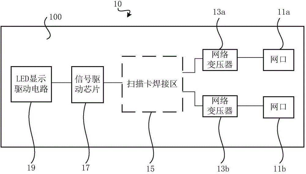
[0027] See figure 1 , an LED light board 10 provided by a preferred embodiment of the present invention, which includes: a first circuit board 100 and network ports 11a, 11b provided on the first circuit board 100, network transformers 13a, 13b, scanning card welding area 15 , a signal driving chip 17 and an LED display driving circuit 19 . Wherein, the network transformer 13a, 13b corresponds to the network port 11a, 11b one by one, the network transformer 13a is electrically connected between the scanning card welding area 15 and the network port 11a, and the network transformer 13b is electrically connected between the scanning card welding area 15 and the network port 11b Between; the signal driving chip 17 is electrically connect...


PUM


Abstract

The invention relates to an LED light panel, scanning card and their combined structure as well as LED display screen control system. The combined structure comprises the LED light panel and the scanning card. The LED light panel comprises a first circuit board, an LED display driving circuit, a signal driving chip, a network transformer and a network port. The first circuit board is provided with a scanning card welding zone. The LED display driving circuit, the signal driving chip, the network transformer and the network port are arranged on the first circuit board. The network transformer is electrically connected between the scanning card welding zone and the network port. The signal driving chip is electrically connected between the LED display driving circuit and the scanning card welding zone. The scanning card is electrically connected to the scanning card welding zone of the first circuit board. According to the invention, complicated and redundant wiring is not required for connections between a scanning card and an LED light panel as well as between the LED light panels in the prior art, therefore, overcoming the shortcomings in wirings.

Description

technical field [0001] The invention relates to the technical field of LED display, in particular to an LED lamp board, a scanning card, a combination structure of the LED lamp board and scanning, and an LED display screen control system. Background technique [0002] In the existing LED display control system, it basically includes a video source, a sending card, a scanning card (or receiving card) and an LED display body; wherein, the video source sends the video signal to the sending card through the video interface, and then sends The card is responsible for converting the video signal into a digital signal and distributing the digital signal, outputting from multiple output interfaces to each scanning card corresponding to the different cabinets connected to it; since the scanning card itself stores the screen parameters of the cabinet where it is located , after the scanning card receives the display data, it will reverse the received data according to the wiring mode ...

Claims


Application Information

Patent Timeline
Patent Type & Authority Applications(China)
IPC IPC(8): G09G3/32
Inventor 周晶晶梁伟杨宏超
Owner XIAN NOVASTAR TECH
Why Eureka
Try Eureka