LED backlight dimming system

A technology of LED backlight and LED lamp, applied in the direction of light source, electric light source, electroluminescence light source, etc., can solve the problems of low reliability, inability to achieve constant current and service life, and achieve high reliability, easy implementation, Simple circuit effect

Pending Publication Date: 2016-12-07
江西康铭盛光电科技有限公司
View PDF16 Cites 15 Cited by
  • Summary
  • Abstract
  • Description
  • Claims
  • Application Information

AI Technical Summary

Problems solved by technology

[0003] There are many kinds of dimming systems for existing LED backlights, among which constant current control is an e

Method used


Image

  • LED backlight dimming system
  • LED backlight dimming system
  • LED backlight dimming system

Examples


Example Embodiment

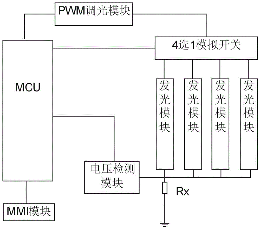
[0046] Example 1: Such as Figure 1 to 3 , An LED backlight dimming system, including MCU, MMI module, PWM dimming module, multiple-choice analog switch and current detection circuit; MCU is a micro processing unit, MMI is a man-machine interface module;

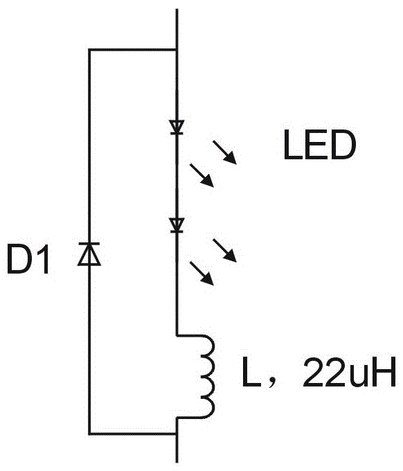
[0047] The LED backlight has multiple LED lights, which are equally divided into N groups to form N light strings in series, and N light-emitting modules are formed based on the N light strings; N is an integer greater than or equal to 2;

[0048] Current detection circuit includes measuring resistance Rx and voltage detection module;

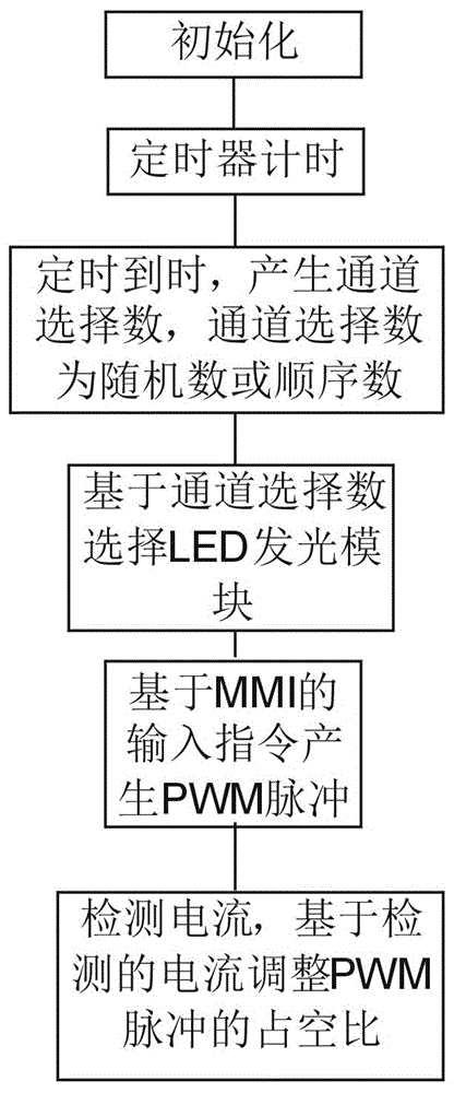
[0049] The one-to-one analog switch has N channels, with N channel branch IO terminals and one common IO terminal; the one-to-multiple analog switch also has a channel selection terminal; the channel selection terminal is connected to the IO port of the MCU; the MCU Output signal to the channel selection terminal to control the conduction of any channel;

[0050] The MCU outputs PWM pulses to the PW...


PUM


Abstract

The invention discloses an LED backlight dimming system. The system comprises an MCU, an MMI module, a PWM dimming module, a selective analog switch and a current detection circuit, wherein the MCU is a microprocessor unit, and the MMI is a man-machine interface module. An LED backlight is provided with multiple LED lamps which are equally divided into N groups to form N string lights connected in series, N light emitting modules are formed based on the N string lights, and N is an integer larger than or equal to 2. The MCU outputs PWM pulse to the PWM dimming module, and the output end of the PWM dimming module is connected with a common IO end of the selective analog switch. The positive electrode ends of the N light emitting modules are connected with N channel branch IO ends of the selective analog switch respectively, and the negative electrode ends of the N light emitting modules are grounded through a measurement resistor Rx. The output end of a voltage detection module is connected with a data input port of the MCU. By the adoption of the LED backlight dimming system, stepless and constant-current dimming can be achieved, and reliability is high.

Description

Technical field [0001] The invention relates to an LED backlight dimming system. Background technique [0002] The most important requirements of the LED backlight module of the display screen for dimming are: 1. Constant current control to avoid flicker, 2. It needs to ensure long-term work and long service life. [0003] There are many types of dimming systems for the existing LED backlights. Among them, constant current control is an existing mature technology, but they cannot guarantee constant current and service life, and their reliability is low; [0004] Therefore, it is necessary to design a more reliable LED backlight dimming system. Summary of the invention [0005] The technical problem to be solved by the present invention is to provide an LED backlight dimming system, which can realize stepless and constant current dimming and has high reliability. [0006] The technical solutions invented are as follows: [0007] An LED backlight dimming system, including MCU, MMI module...

Claims


Application Information

Patent Timeline
IPC IPC(8): G09G3/34H05B33/08H05B44/00
CPCG09G3/3406H05B45/00
Inventor 李迪初聂卫陶正佳
Owner 江西康铭盛光电科技有限公司
Why Eureka
Try Eureka