Low-power UPS

A low-power, transformer technology, applied in electrical components, emergency power arrangements, circuit devices, etc., can solve problems such as inability to work, large isolation transformers, and reduced UPS reliability, and achieve high reliability and small size.

Inactive Publication Date: 2016-12-07
EAST GRP CO LTD
5 Cites 0 Cited by

AI-Extracted Technical Summary

Problems solved by technology

The volume of the isolation transformer is large, which is not conducive to the miniaturization of UPS
In addition, the mains mode and the battery mode shar...

Abstract

The invention discloses a low-power UPS, and relates to the technical field of the uninterruptible power supply (UPS). The low-power UPS comprises a storage battery, a charging unit, an inversion unit, a transformer for voltage stabilization, and an output unit which is used for outputting outwardly, wherein when the low-power UPS works in a mains supply mode, the charging unit takes power from the mains supply to charge the storage battery; the transformer takes power from the mains supply, performs voltage stabilization and then outputs the power to the output unit; the transformer is an autotransformer; the low-power UPS also comprises a DC/DC conversion unit; when the low-power UPS works in a battery mode, the electric energy output by the storage battery is subjected to voltage conversion by the DC/DC conversion unit, and then the electric energy is output to the inversion unit; and next, the electric energy is inverted into alternating current by the inversion unit, and finally the alternating current is output to the output unit.

Application Domain

Emergency power supply arrangements

Technology Topic

Electrical batteryElectric energy +7

Image

  • Low-power UPS
  • Low-power UPS

Examples

  • Experimental program(1)

Example Embodiment

[0014] The invention will be described in detail below in conjunction with specific embodiments.
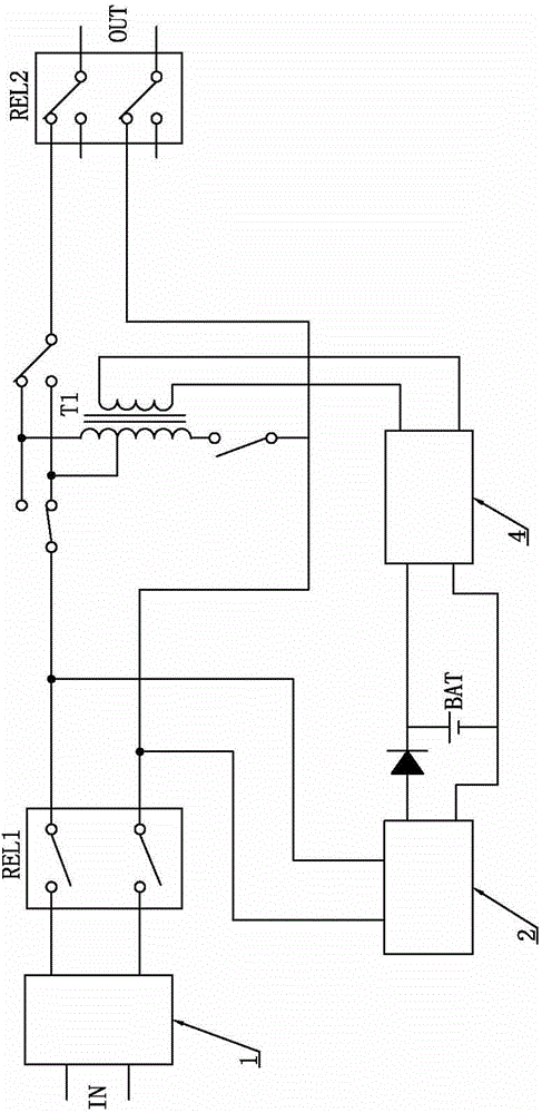
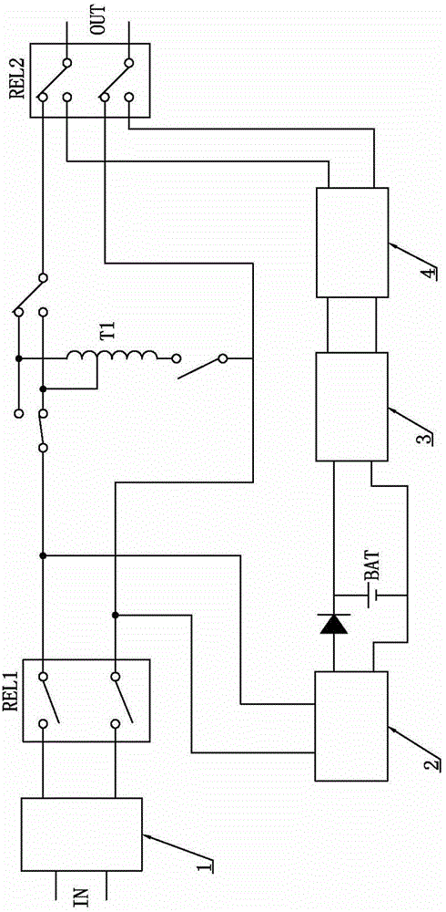
[0015] like figure 2 As shown, the low-power UPS of this embodiment includes an input filter unit 1, an input relay REL1, a transformer T1, a charging unit 2, a battery BAT, a DC/DC conversion unit 3, an inverter unit 4 and an output relay REL3, and the transformer T1 is an automatic The coupling transformer, the DC/DC conversion unit 3 is a boost circuit, the output relay REL3 constitutes the output unit, the IN terminal is the mains input terminal, and the OUT terminal is the output terminal of the low-power UPS in this embodiment.
[0016] When the mains is normal, the input relay REL1 pulls in, and the output relay REL3 connects the output terminal of the transformer T1 to the output terminal OUT of the low-power UPS of this embodiment, thereby switching the working mode of the low-power UPS of this embodiment to the mains mode . After the input filter unit 1 filters the mains power, one output is sent to the charging unit 2, and the charging unit 2 charges the battery BAT, and the other one is output to the transformer T1 through the input relay REL1, and the transformer T1 stabilizes the mains voltage and passes through the output relay REL3 output to the load.
[0017] When the mains power is abnormal, the input relay REL1 is disconnected, and the output relay REL3 connects the output terminal of the inverter unit 4 to the output terminal OUT of the low-power UPS of this embodiment, thereby switching the working mode of the low-power UPS of this embodiment to battery model. The battery BAT outputs direct current to the DC/DC conversion unit 3, and the DC/DC conversion unit 3 boosts the direct current, and then is converted into alternating current by the inverter unit 4, and then output to the output relay REL3, and output to the load through the output terminal OUT .
[0018] Since the DC power output by the battery BAT in the battery mode is converted after DC boost by the DC/DC conversion unit 3, the voltage is not boosted by the transformer T1, and the transformer T1 is only used to stabilize the mains voltage in the mains power mode , so the transformer T1 adopts an autotransformer, and the volume of the autotransformer is small, which is beneficial to the miniaturization of the low-power UPS in this embodiment. Depend on figure 2 It can be seen intuitively that the mains mode circuit and the battery mode circuit are independent of each other, even if the transformer T1 fails, the battery mode is not affected and can still work normally. In addition, in the low-power UPS of this embodiment, both the DC/DC conversion unit 3 and the inverter unit 4 can adopt a high-frequency operation mode, and the high-frequency operation mode makes the UPS miniaturized and has better heat dissipation performance.
[0019] Finally, it should be noted that the above examples are only used to illustrate the technical solutions of the present invention, rather than to limit the protection scope of the present invention. Although the present invention has been described in detail with reference to the preferred embodiments, those skilled in the art Personnel should understand that the technical solution of the present invention can be modified or equivalently replaced without departing from the essence and scope of the technical solution of the present invention.

PUM

no PUM

Description & Claims & Application Information

We can also present the details of the Description, Claims and Application information to help users get a comprehensive understanding of the technical details of the patent, such as background art, summary of invention, brief description of drawings, description of embodiments, and other original content. On the other hand, users can also determine the specific scope of protection of the technology through the list of claims; as well as understand the changes in the life cycle of the technology with the presentation of the patent timeline. Login to view more.

Similar technology patents

Two fluid pump

InactiveUS20130206794A1reduce volumevolume greatly expand
Owner:GOJO IND INC

Identification Attachments

ActiveUS20080230509A1reduce volumeminimise amount
Owner:ITW NEW ZEALAND

Classification and recommendation of technical efficacy words

  • Improve reliability
  • reduce volume

Multiple branch predictions

ActiveUS20050268075A1improve reliabilityfacilitate availability
Owner:ORACLE INT CORP

Implantable lead

ActiveUS20100137928A1good flexibility , fatigue resistance and flex lifeimprove reliability
Owner:WL GORE & ASSOC INC

Implant release mechanism

ActiveUS20080140178A1reduce volumereduce outer diameter
Owner:COOK MEDICAL TECH LLC

Speed reduction box for turbine fracturing

Owner:YANTAI JEREH PETROLEUM EQUIP & TECH

Miniature and Multi-Band RF Coil Design

ActiveUS20100090824A1reduce volumelong wavelength
Owner:HONG KONG APPLIED SCI & TECH RES INST

Automatic washing and dewatering combined device of rotary type mop

InactiveCN102370447Areduce volumeSimple structure
Owner:上海祥美网络科技有限公司 +1

Optical imaging system

ActiveUS20070008625A1reduce volumedeteriorate with time
Owner:SAMSUNG ELECTRONICS CO LTD
Why Eureka
Try Eureka