Acoustic impedance matching device and method based on piezoelectric effect
A piezoelectric effect and matching device technology, applied in the direction of impedance network, electrical components, etc., can solve the problem that it is difficult to meet the needs of transducer load impedance matching, and achieve the effect of reducing costs
- Summary
- Abstract
- Description
- Claims
- Application Information
AI Technical Summary
Problems solved by technology
Method used
Image

Examples
Embodiment 1
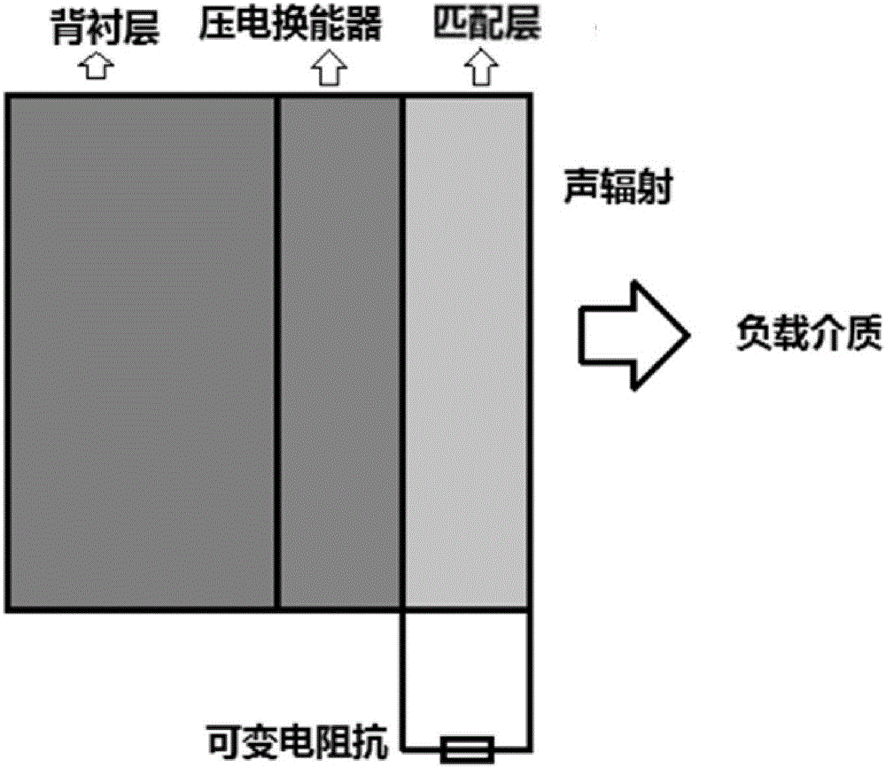
[0023] like figure 2 As shown, the acoustic impedance matching device based on the piezoelectric effect includes a backing layer, a piezoelectric transducer and a matching layer, wherein the matching layer adopts a piezoelectric ceramic matching layer structure, and the two electrode surfaces of the matching layer are connected with An electrical impedance whose value can be changed.
[0024] The above-mentioned electrical impedance can be resistance, inductance, capacitance, or any two series-parallel impedances of resistance, inductance, and capacitance, or the series-parallel impedance of the three. By changing the electrical impedance, the mechanical impedance of the piezoelectric ceramic matching layer can be changed, and then the change can be achieved. Ideal match to the load impedance of the transducer.
[0025] The structure of the piezoelectric ceramic matching layer is a thickness-polarized piezoelectric ceramic disc, and the two ends of the piezoelectric ceramic ...
Embodiment 2
[0027] like figure 2 Shown, the acoustic impedance matching method based on piezoelectric effect of the present invention, comprises the following steps:
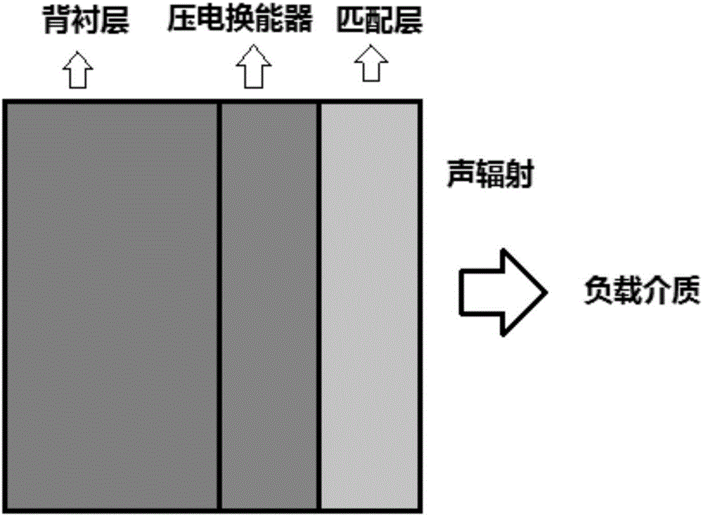
[0028] Step 1. Under the action of an external electrical signal, the piezoelectric transducer converts electrical energy into mechanical energy by means of the piezoelectric effect to generate mechanical vibration. The mechanical vibration is divided into two parts;
[0029] Step 2. Part of the mechanical vibration propagates into the backing layer of the piezoelectric transducer and is absorbed by the backing layer; the other part of the mechanical vibration propagates into the matching layer of the piezoelectric transducer and enters the load medium through the matching layer .
[0030] Based on the piezoelectric effect of piezoelectric ceramic materials, the acoustic impedance matching of the piezoelectric transducer can be carried out through the above steps, so that the mechanical vibration generated by the piezoele...
Embodiment 3
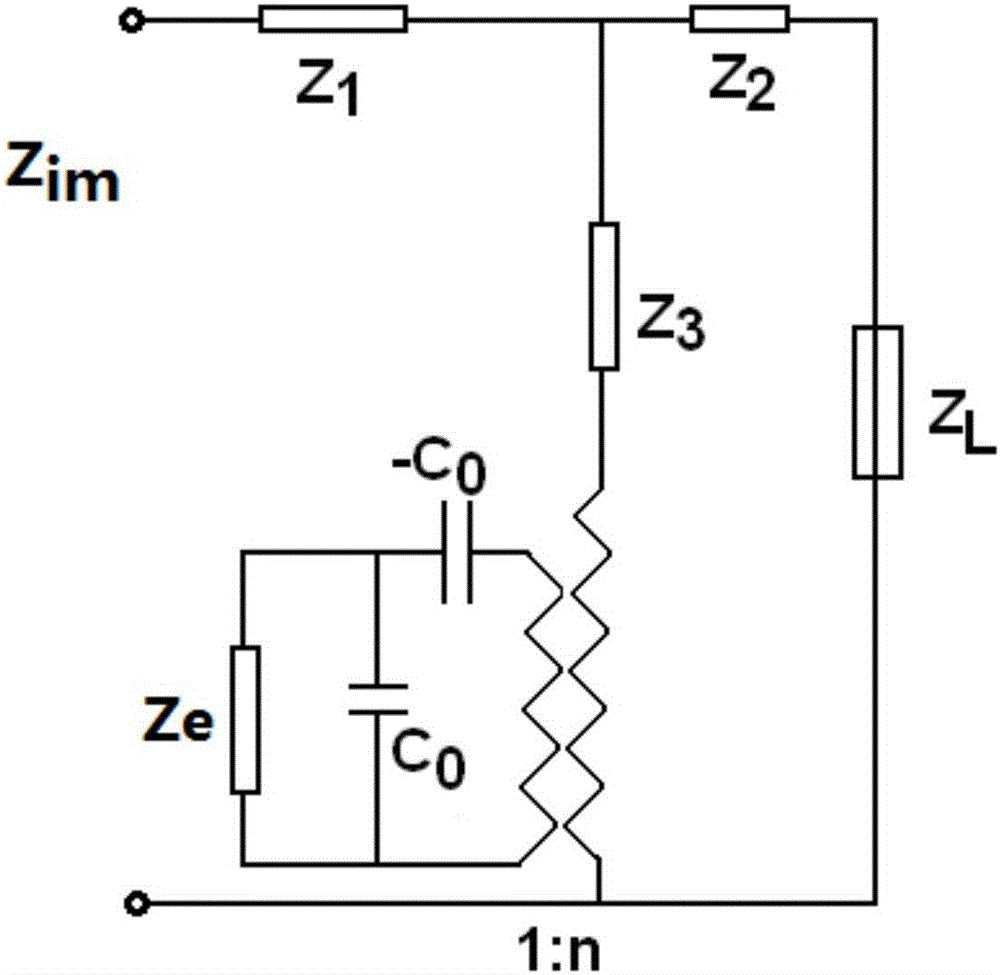
[0032] On the basis of the above examples, if image 3 Shown, the electromechanical equivalent circuit diagram of the matching layer in the acoustic impedance matching method based on piezoelectric effect of the present invention, among the figure Z 1 ,Z 2 ,Z 3 is the equivalent circuit impedance of the piezoceramic matching layer, C 0 is the static capacitance of the piezoelectric ceramic matching layer, and n is the electromechanical conversion coefficient of the piezoelectric ceramic matching layer material. Ze is a variable electrical impedance connected to both ends of the piezoelectric ceramic matching layer, and the electrical impedance can be resistance, inductance, capacitance or any series-parallel compound between the three. Z L is the load impedance of the transducer radiation medium, that is, the load impedance of the transducer before matching, and Zim is the input mechanical impedance of the piezoelectric ceramic matching layer after matching with the piezoe...
PUM
| Property | Measurement | Unit |
|---|---|---|
| Radius | aaaaa | aaaaa |
| Thickness | aaaaa | aaaaa |
Abstract
Description
Claims
Application Information
 - R&D
- Intellectual Property
- Life Sciences
- Materials
- Tech Scout
- Unparalleled Data Quality
- Higher Quality Content
- 60% Fewer Hallucinations
Browse by: Latest US Patents, China's latest patents, Technical Efficacy Thesaurus, Application Domain, Technology Topic, Popular Technical Reports.
© 2025 PatSnap. All rights reserved.Legal|Privacy policy|Modern Slavery Act Transparency Statement|Sitemap|About US| Contact US: help@patsnap.com