Method, device and system for tracking electromagnetic wave propagation path

A technology of transmission path and tracking device, which is applied in the field of communication, can solve problems such as time-consuming and complicated calculation process, and achieve the effect of reducing complexity

Active Publication Date: 2019-09-13
FUJITSU LTD
View PDF3 Cites 0 Cited by
  • Summary
  • Abstract
  • Description
  • Claims
  • Application Information

AI Technical Summary

Problems solved by technology

In the mirroring method, the depth calculation of the mirroring point determines the accuracy of the modeling method, so for a relatively complex and large-scale scene, the process of solving the mirroring point will make the calculation process very complicated and time-consuming

Method used


Image

  • Method, device and system for tracking electromagnetic wave propagation path
  • Method, device and system for tracking electromagnetic wave propagation path
  • Method, device and system for tracking electromagnetic wave propagation path

Examples


Embodiment 1

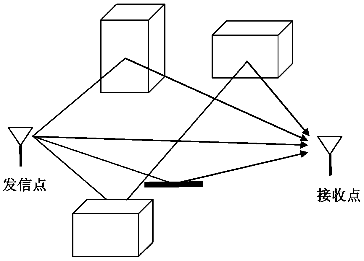
[0053] An embodiment of the present invention provides a method for tracking an electromagnetic wave propagation path. The method is applied to a wireless signal propagation scenario, and the establishment process of the propagation scenario is as described above. Figure 6 is the flowchart of the method, please refer to Figure 6 , the method includes:

[0054] Step 601: Determine the effective plane of the sending point according to the preset effective plane selection radius;

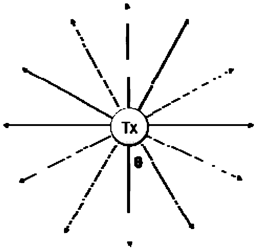
[0055] Step 602: For each ray sent by the sending point, detect the intersection between the ray and the effective plane along the direction of the ray;

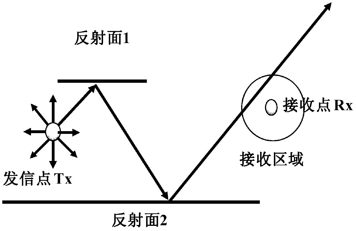
[0056] Step 603: If there is an intersection point between the ray and the effective plane, and the cumulative reflection equivalent of the path of the ray passing through the effective intersection is not greater than the preset maximum reflection equivalent, determine the next path direction of the ray, Until the ray reaches the receiving area ...

Embodiment 2

[0120] The embodiment of the present invention also provides a tracking device for the propagation path of electromagnetic waves. Since the problem-solving principle of the device is similar to that of the method in embodiment 1, its specific implementation can refer to the implementation of the method in embodiment 1. The content is the same The description will not be repeated.

[0121] Figure 16 It is a schematic diagram of the composition of the tracking device of the electromagnetic wave propagation path in this embodiment, please refer to Figure 16 , the apparatus 1600 includes: a determination unit 1601, a detection unit 1602, and a processing unit 1603, wherein:

[0122] The determining unit 1601 is configured to determine an effective plane of a sending point according to a preset effective plane selection radius.

[0123] Wherein, as described in Embodiment 1, in the wireless signal propagation scenario, if the distance from a certain plane of an obstacle to the ...

Embodiment 3

[0134] An embodiment of the present invention also provides a computer system, which may include the device for tracking the electromagnetic wave propagation path described in Embodiment 2.

[0135] Figure 17 is a schematic diagram of the composition of the computer system of this embodiment, such as Figure 17 As shown, the computer system 1700 may include: a central processing unit (CPU) 1701 and a memory 1702; the memory 1702 is coupled to the central processing unit 1701. Among them, the memory 1702 can store various data; in addition, it also stores information processing programs, and executes the programs under the control of the central processing unit 1701 .

[0136] In one embodiment, the function of the tracking device for the electromagnetic wave propagation path described in Embodiment 2 may be integrated into the central processing unit 1701 .

[0137] In another embodiment, the tracking device of the electromagnetic wave propagation path as described in Embod...


PUM


Abstract

The embodiment of the invention provides an electromagnetic wave propagation path ray-tracing method, device and system. The method comprises the steps of determining an effective plane of a signal sending point according to a preset effective plane selection radius; for each ray sent by the signal sending point, detecting an intersection point between the ray and the effective plane along the direction of the ray; and determining a next path direction of the ray, until the ray arrives at a receiving area of a receiving point or the accumulated reflection equivalent of the path of the ray passing the effective intersection point is more than the preset maximum reflection equivalent, if the intersection point exists between the ray and the effective plane and the accumulated reflection equivalent of the path of the ray passing the effective intersection point is not more than the preset maximum reflection equivalent. Through application of the embodiment of the method, the device and the system, the complexity of the calculation process in the path ray-tracing process is reduced, the high-efficiency and accurate electromagnetic wave propagation path simulation is realized, and the electromagnetic wave propagation characteristic in an observed wireless network can be obtained.

Description

technical field [0001] The present invention relates to the field of communication technology, in particular to a method, device and system for tracking electromagnetic wave propagation paths. Background technique [0002] With the rapid development of wireless communication today, various wireless applications serving human life and work are increasing day by day. It follows that the performance requirements of the wireless communication system for applications based on various services are also constantly improving. According to different application requirements, wireless communication systems are often deployed in various environmental scenarios, such as an urban environment with many buildings, an open suburban environment without shelter, and a forest environment with lush vegetation, etc. How to understand the propagation characteristics of the wireless system in a specific environment is undoubtedly of great significance for the prediction of the signal field streng...

Claims


Application Information

Patent Timeline
Patent Type & Authority Patents(China)
IPC IPC(8): H04B17/30H04B17/391
Inventor 奥琛李红春田军
Owner FUJITSU LTD
Why Eureka
Try Eureka