
Analytical method for slippery limit condition and cooling flow demand of wet dual clutch

A technology of wet double clutch and extreme working conditions, which is applied to clutches, instruments, mechanical equipment, etc., can solve problems such as overheating, friction material surface burnout of clutches, and affecting driving safety, etc., to achieve prevention of burnout, fast speed, simulation Simulate the effect of low cost

Active Publication Date: 2021-12-03
BORGWARNER AUTOMOTIVE COMPONENTS (NINGBO) CO LTD
View PDF3 Cites 0 Cited by
  • Summary
  • Abstract
  • Description
  • Claims
  • Application Information

AI Technical Summary

Problems solved by technology

[0003] Under extremely harsh working conditions, such as when starting on a slope, the wet dual clutch will generate a large amount of frictional heat due to the sliding friction of the friction plate. If the lubrication and cooling flow is insufficient and the frictional heat cannot be taken away in time, the friction surface of the clutch will overheat and stay in an overheated state for a long time It will cause the surface of the friction material of the clutch to be burned and the function will fail, which will greatly affect the driving safety.

Method used


Image

  • Analytical method for slippery limit condition and cooling flow demand of wet dual clutch
  • Analytical method for slippery limit condition and cooling flow demand of wet dual clutch
  • Analytical method for slippery limit condition and cooling flow demand of wet dual clutch

Examples


Embodiment Construction

[0025] In the following, the analysis method for the wet dual-clutch sliding friction limit condition and cooling flow demand of the present invention will be described in detail in conjunction with the accompanying drawings and specific embodiments.

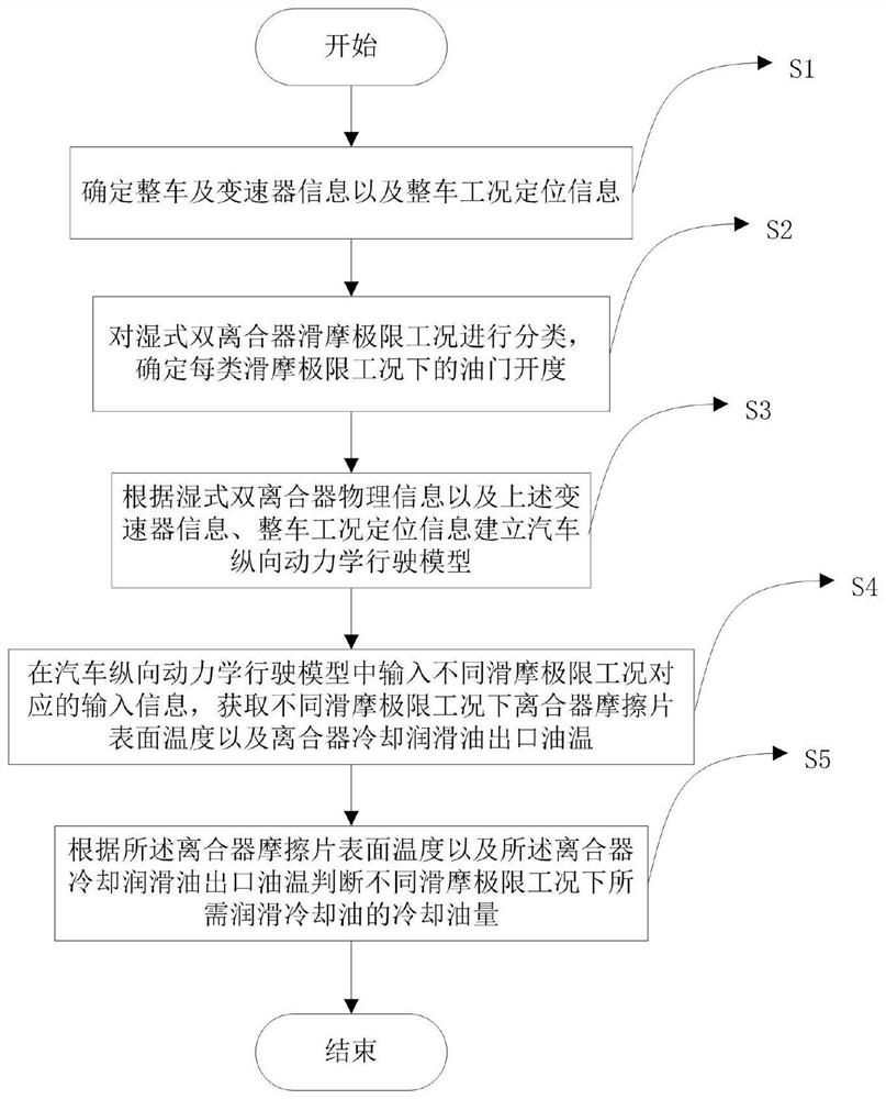
[0026] Such as figure 1 As shown, the wet dual clutch sliding limit condition and cooling flow demand analysis method includes steps:

[0027] S1. Determine the vehicle and transmission information and the positioning information of the vehicle working condition;

[0028] S2. Classify the slippery limit conditions of the wet dual clutch, and determine the throttle opening under each type of slippery limit conditions;

[0029] S3. Establishing a vehicle longitudinal dynamics driving model according to the physical information of the wet dual clutch, the above-mentioned transmission information, and the positioning information of the vehicle working condition;

[0030] S4. Input the input information corresponding to different s...


PUM


Abstract

The present invention provides a wet dual-clutch sliding limit working condition and a cooling flow demand analysis method, comprising the steps of: determining the vehicle and transmission information and the positioning information of the vehicle working condition; classifying the wet dual-clutch sliding friction limit working condition, determining Accelerator opening under each type of sliding friction limit condition; establish a vehicle longitudinal dynamics driving model based on the physical information of the wet dual clutch, the above transmission information, and vehicle working condition positioning information; input different sliding frictions into the vehicle longitudinal dynamics driving model The input information corresponding to the limit working conditions is used to obtain the surface temperature of the clutch friction plate and the outlet oil temperature of the clutch cooling lubricating oil under different sliding friction limit conditions; according to the surface temperature of the clutch friction plate and the oil temperature of the clutch cooling lubricating oil outlet The amount of cooling oil required for lubricating cooling oil under certain conditions. This method simulates with low cost and high speed.

Description

technical field [0001] The invention relates to the field of automobiles, in particular to a wet dual-clutch sliding friction limit working condition and a cooling flow demand analysis method. Background technique [0002] As one of the core components of the automobile transmission system, the clutch is connected between the engine and the transmission in the transmission system. Under running conditions, with appropriate gears, power transmission efficiency and fuel economy can be improved. The dual-clutch automatic transmission contains two clutches to control the odd and even gears respectively. The odd and even clutches work alternately to reduce the impact caused by power interruption and improve the smoothness and comfort of shifting. From the different contact forms and cooling methods on the surface of the dual clutch, it is divided into a dry dual clutch and a wet dual clutch. The dry dual clutch mainly cools the heat generated during the clutch friction process t...

Claims


Application Information

Patent Timeline
Patent Type & Authority Patents(China)
IPC IPC(8): G06F30/15F16D48/02G06F119/08G06F119/14
CPCF16D48/02G06F30/15G06F2119/06G06F2119/08Y02T90/00
Inventor 赵力涂培章曾俊林程荣振袁峥正
Owner BORGWARNER AUTOMOTIVE COMPONENTS (NINGBO) CO LTD
Learn More