Rotary cutting die for pipe fittings

A technology for molds and pipe fittings, applied in the field of pipe rotary cutting molds, can solve problems such as low work efficiency, unstable positioning, and inability to meet production efficiency, and achieve the effects of improving efficiency, avoiding uneven incisions, and stable positioning

Inactive Publication Date: 2016-12-14
NANJING HUIDE MACHINERY
View PDF8 Cites 2 Cited by
  • Summary
  • Abstract
  • Description
  • Claims
  • Application Information

AI Technical Summary

Problems solved by technology

[0002] The existing pipe fitting notching die structure is to cut the edge from top to bottom, and a single punching can only punch one side, and some pipe fittings that cut both sides need to be punched twice, the work efficiency is low, the positioning is unstable, and it cannot meet the current requirements. Productivity

Method used


Image

  • Rotary cutting die for pipe fittings
  • Rotary cutting die for pipe fittings
  • Rotary cutting die for pipe fittings

Examples


Embodiment 1

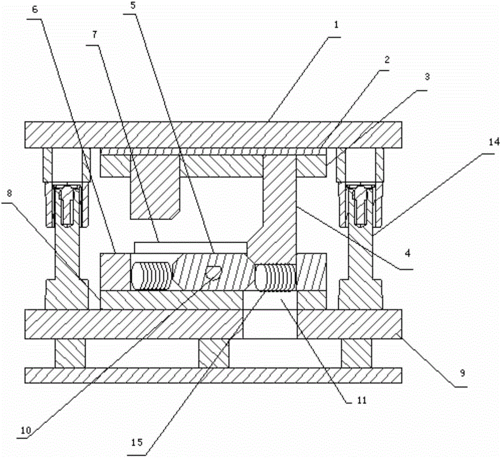
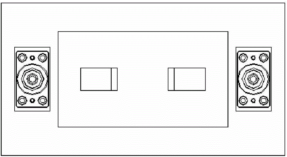
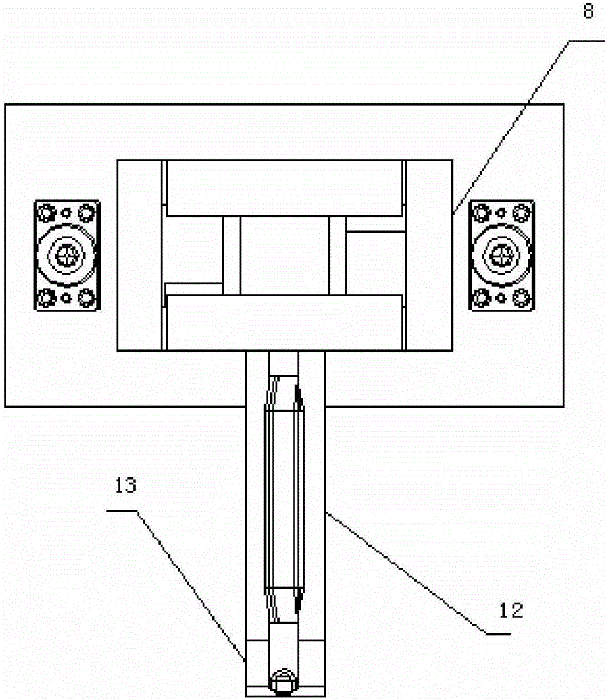
[0023] This embodiment provides a pipe fitting rotary cutting die, the structure is as follows Figure 1-3 As shown, it includes upper mold base 1, backing plate 2, upper clamping plate 3, bevel drive block 4, lower slider 5, return spring 15, side stopper 6, product positioning block, lower clamping plate 8 and lower mold base 9 , the backing plate 2 is affixed to the bottom of the upper mold base 1, the upper splint 3 is affixed to the bottom of the backing plate 2, and the bevel drive block 4 is fixed to the two ends of the bottom of the upper splint 3, and the height is different, the bevel drive block 4 Respectively against the side stopper 6 and the lower slider 5, the two ends of the return spring 15 are respectively against the side stopper 6 and the lower slider 5, and the middle part of the lower slider 5 is provided with a knife-edge groove 10, which is a sliding structure , and the knife-edge groove 10 is provided with a knife-edge mandrel, the side stopper 6 and t...

Embodiment 2

[0028] This embodiment provides a pipe fitting rotary cutting die, the structure is as follows Figure 1-3 As shown, it includes upper mold base 1, backing plate 2, upper clamping plate 3, bevel drive block 4, lower slider 5, return spring 15, side stopper 6, product positioning block, lower clamping plate 8 and lower mold base 9 , the backing plate 2 is affixed to the bottom of the upper mold base 1, the upper splint 3 is affixed to the bottom of the backing plate 2, and the bevel drive block 4 is fixed to the two ends of the bottom of the upper splint 3, and the height is different, the bevel drive block 4 Respectively against the side stopper 6 and the lower slider 5, the two ends of the return spring 15 are respectively against the side stopper 6 and the lower slider 5, and the middle part of the lower slider 5 is provided with a knife-edge groove 10, which is a sliding structure , and the knife-edge groove 10 is provided with a knife-edge mandrel, the side stopper 6 and t...


PUM


Abstract

The invention discloses a rotary cutting die for pipe fittings. The rotary cutting die comprises a punch set, a bolster, a punch holder, an inclined block drive block, a lower slide block, return springs, side stop blocks, a product locking block and a die set, wherein the bolster is fixedly connected at the bottom end of the punch set, the punch holder is fixedly connected at the bottom of the bolster, the inclined block drive block is fixed at two bottom ends of the punch holder and abuts against the side stop blocks and the lower slide block, the two ends of each return spring abut against the corresponding side stop block and the lower slide block, a cutter slot is formed in the middle of the lower slide block, the side stop blocks and the lower slide block are fixed on a die holder, the product locking block is fixed on the die holder through a locking plate, and the die holder is fixed on the die holder. The rotary cutting die for the pipe fittings has the advantages of high strength, high tenacity, operational simplicity and stability, high working efficiency and long service life.

Description

technical field [0001] The invention relates to the technical field of pipe fitting molds, in particular to a pipe fitting rotary cutting mold. Background technique [0002] The existing pipe fitting notching die structure is to cut the edge from top to bottom, and a single punching can only punch one side, and some pipe fittings that cut both sides need to be punched twice, the work efficiency is low, the positioning is unstable, and it cannot meet the current requirements. Productivity. Contents of the invention [0003] The technical problem to be solved by the present invention is to overcome the shortcomings of the prior art and provide a rotary cutting die for pipe fittings with simple operation, stability and high working efficiency. [0004] The technical solution of the present invention to solve the above technical problems is to provide a rotary cutting mold for pipe fittings, including an upper mold base, a backing plate, an upper splint, a bevel drive block, ...

Claims


Application Information

Patent Timeline
Patent Type & Authority Applications(China)
IPC IPC(8): B21D28/14B21D28/04B21D37/01C22C38/54C22C38/04C22C38/50C22C38/48C22C38/02C22C38/06C22C38/42C22C38/46C22C38/44C22C38/52
CPCB21D28/14B21D28/04B21D37/01C22C38/001C22C38/002C22C38/005C22C38/02C22C38/04C22C38/06C22C38/42C22C38/44C22C38/46C22C38/48C22C38/50C22C38/52C22C38/54
Inventor 张国营刘圣祖
Owner NANJING HUIDE MACHINERY
Why Eureka
Try Eureka