
A Boiler Header Tube Hole Processing Tool

A technology for boiler headers and processing tools, which is applied in the direction of manufacturing tools, metal processing equipment, drilling accessories, etc., can solve the problems that it is difficult to ensure the size requirements of the tube holes, the size accuracy of the tube holes cannot be guaranteed, and waste of time, etc., to achieve Save processing time, ensure molding size, and reduce processing times

Active Publication Date: 2018-02-06
HARBIN HAGUO BOILER ENG TECH
View PDF7 Cites 0 Cited by
  • Summary
  • Abstract
  • Description
  • Claims
  • Application Information

AI Technical Summary

Problems solved by technology

[0003] The present invention solves the need to process the tube holes of the existing boiler header three times, which is a waste of time, and requires frequent replacement of the cutter bar and the blade. Manual operation cannot guarantee the dimensional accuracy of the tube holes, and it is difficult to ensure the tube holes when processing the tube holes. The problem of size requirements, and then provide a boiler header tube hole processing tool

Method used


Image

  • A Boiler Header Tube Hole Processing Tool
  • A Boiler Header Tube Hole Processing Tool
  • A Boiler Header Tube Hole Processing Tool

Examples


specific Embodiment approach 1

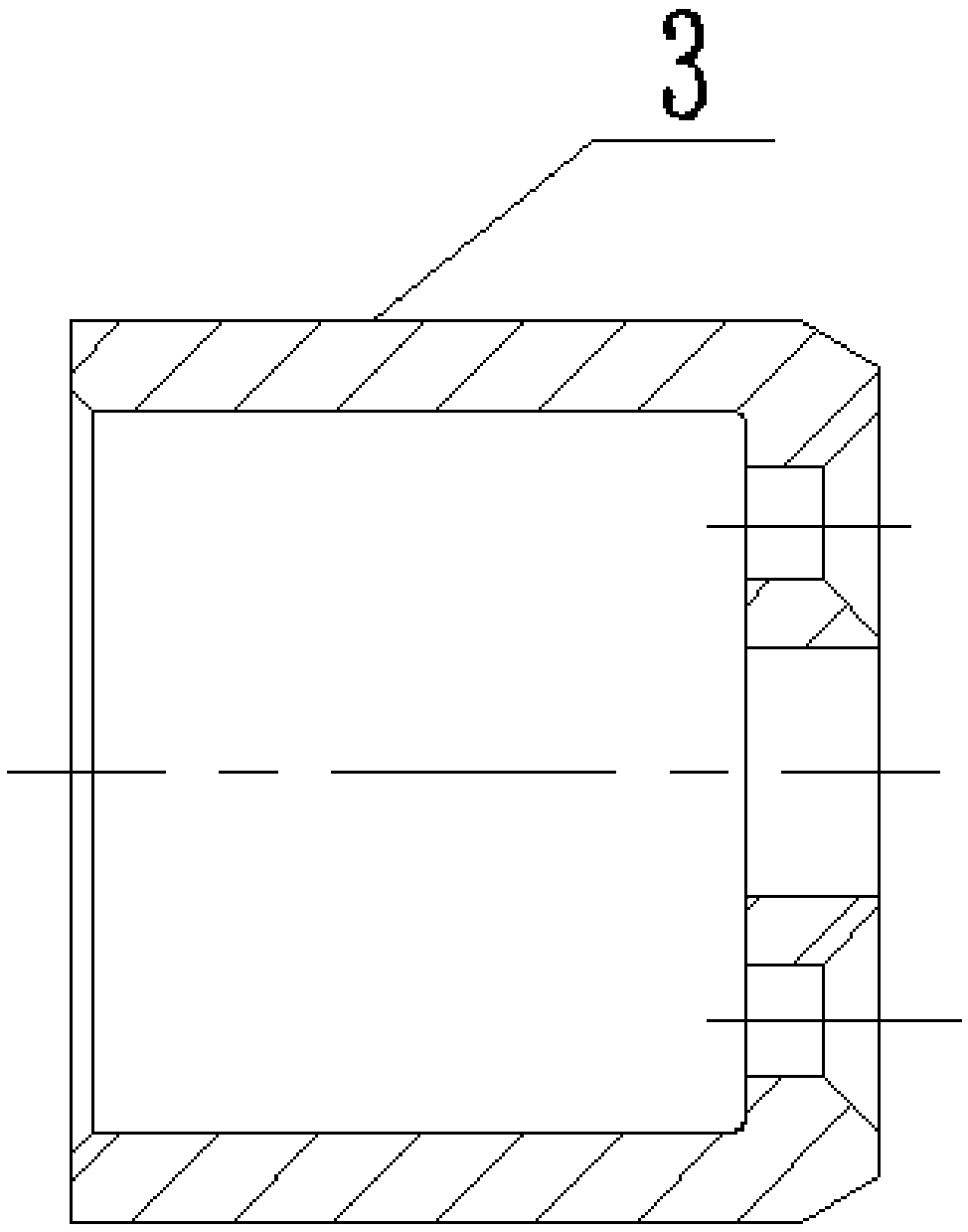
[0008] Specific implementation mode one: combine Figure 2-Figure 10 Describe this embodiment, a boiler header pipe hole processing tool described in this embodiment, it includes a bolt 1, a guide sleeve 3, a blade 4, and a cutter bar 5, a blade tightening screw 6 and two guide sleeve fixing screws 2 , the tool bar 5 includes a flat section 5-1, a conical section 5-2, a blade installation section 5-3 and a guide sleeve fixing section 5-4, and the flat section 5-1, a conical section 5-2, and a blade installation section 5- 3 and the guide sleeve fixed section 5-4 are fixedly connected in sequence, and the guide sleeve fixed section 5-4 is processed with two guide sleeve fixing screw threaded holes along the length direction of the cutter bar 5, and the blade installation section 5-3 is close to the guide sleeve The fixed section 5-4 is processed with a plane 5-5 and the blade installation hole 5-6, and the blade top tightening screw thread hole is processed on the plane 5-5 to ...

specific Embodiment approach 2

[0009] Specific implementation mode two: combination figure 2 , Figure 4-Figure 8 Describe this embodiment, a boiler header tube hole processing tool described in this embodiment, the blade 4 includes a first blade portion 4-1, a second blade portion 4-2 and a cutter body 4-3, the first blade portion 4 -1 is positioned at the top of the front end face 4-4 of the cutter body 4-3, and the second blade portion 4-2 is positioned at the bottom end of the cutter body 4-3, and the main blade of the second blade portion 4-2 is connected to the front end face 4 The angle formed by the vertical planes of -4 is c, the first chip flute is processed on the first blade portion 4-1, the rake angle of the first blade portion 4-1 is a1, the first blade portion 4-1 The relief angle is b1, the second flute is processed on the second blade portion 4-2, the rake angle of the second blade portion 4-2 is a2, the relief angle of the second blade portion 4-2 is b2, and the first The distance betwe...

specific Embodiment approach 3

[0010] Specific implementation mode three: combination figure 2 , Figure 4-Figure 8 Describe this embodiment, a boiler header pipe hole processing tool described in this embodiment, the value of a1 is 8°, the value of b1 is 12°, the value of a2 is 12°, and the value of b2 is 8°, The value of c is 45°, the value range of L is 2mm-4mm, and other components and connections are the same as those in the second embodiment.


PUM


Abstract

The invention discloses a boiler header pipe hole machining tool, relates to a pipe hole machining tool, and aims to solve the problems of time waste due to need of triple machining, need of frequent replacement of a cutter bar and a blade, incapability of guaranteeing the pipe hole size precision in manual operation and difficult guarantee of the pipe hole size requirements in pipe hole machining in traditional boiler head pipe hole machining. The boiler header pipe hole machining tool comprises a bolt, a guide sleeve, a blade, a cutter bar, blade ejecting screws and two guide sleeve fixed screws; the cutter bar includes a flat section, a conical section, a blade mounting section and a guide sleeve fixed section; the flat section, the conical section, the blade mounting section and the guide sleeve fixed section are fixedly connected in sequence; a plane and a blade mounting hole are machined on the blade mounting section; blade ejecting screw thread holes are formed from the plane to the blade mounting hole; the guide sleeve coats the guide sleeve fixed section; the blade is mounted in the blade mounting hole; and the blade ejecting screws are arranged in the blade ejecting screw thread holes. The boiler header pipe hole machining tool is used for header pipe hole machining.

Description

technical field [0001] The invention relates to a pipe hole processing tool, in particular to a boiler header pipe hole processing tool. Background technique [0002] In boiler manufacturing, the header is its main component. At present, most of the tube holes in the header manufacturing of 300MW, 600MW and other large-capacity boilers are made by first processing the A size with a drill, and then processing the B size separately with different white steel knives. , C size. This method needs to be processed three times, and the tool holder and blade need to be replaced frequently. It is a waste of time, and when using a white steel knife (aspect, long strip) to process the dimensions B and C, it is necessary to grind the dimensions of the B and C shapes according to the drawing size. Since the material of the white steel knife is relatively hard, it is time-consuming and laborious to grind , and manual operation cannot guarantee the dimensional deviation, it is difficult t...

Claims


Application Information

Patent Timeline
Patent Type & Authority Patents(China)
IPC IPC(8): B23B51/08
CPCB23B51/08
Inventor 赵国洋祝应时王雪飞袁兴爽奚晓娟
Owner HARBIN HAGUO BOILER ENG TECH
Learn More