Automatic clamping pipe cutting machine

An automatic clamping and pipe cutting machine technology, applied in clamping, pipe shearing devices, shearing devices, etc., can solve the problems of reducing production efficiency and manpower consumption, and achieve the goal of improving work efficiency, satisfying cutting requirements, and reducing labor force Effect

Inactive Publication Date: 2016-12-14
卢道东
View PDF0 Cites 10 Cited by
  • Summary
  • Abstract
  • Description
  • Claims
  • Application Information

AI Technical Summary

Problems solved by technology

[0002] Traditional pipe cutting machines require manual feeding and discharging when cutting steel pipes, which consumes manpower and reduces production efficiency

Method used


Image

  • Automatic clamping pipe cutting machine
  • Automatic clamping pipe cutting machine
  • Automatic clamping pipe cutting machine

Examples


Embodiment Construction

[0016] The present invention will be described in further detail below through specific implementation examples and in conjunction with the accompanying drawings.

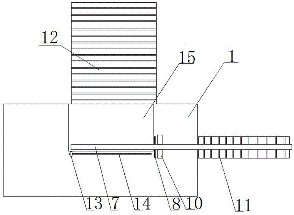
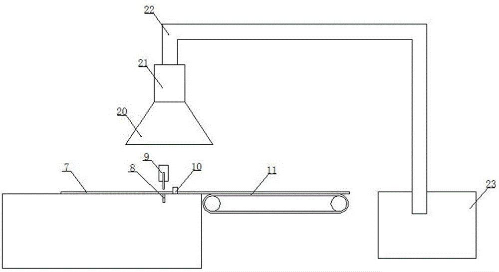
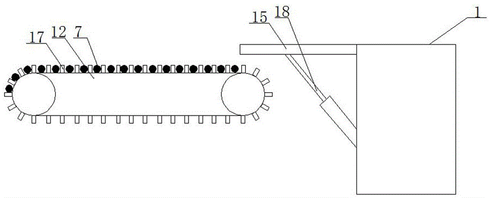
[0017] Figure 1-3 Shown is an automatic clamping pipe cutting machine provided by the present invention, including: steel pipe 7, cutting groove 8, cutting device 9, electromagnet clamping block 10, feed conveyor belt 11, discharge conveyor belt 12, Infrared sensor 13, chute 14, rotating plate 15, raised bar 17, cylinder 18 and body working surface 1. A pair of electromagnet clamping blocks 10 and an infrared sensor 13 can be slidably provided on the working surface 1 of the body; a cutting device 9 is provided on the working surface 1 of the body, and the knife edge of the cutting device 9 is between the moving end of the infrared sensor 13 A scale is provided; the body working surface 1 is rotatably provided with a rotating plate 15 flush with it, a cylinder 18 is provided between the rotating plate 15 and the ...


PUM


Abstract

The invention discloses an automatic clamping pipe cutting machine. The automatic clamping pipe cutting machine comprises a machine body working surface. The machine body working surface is slidably provided with a pair of electromagnet clamping blocks and an infrared sensor. A cutting device is arranged on the machine body working surface. A scale ruler is arranged between a knife edge of the cutting device and the movement tail end of the infrared sensor. The machine body working surface is rotationally provided with a rotating plate flush with the machine body working surface. An air cylinder is arranged between the rotating plate and a machine body, and a discharging conveying belt is arranged on one side of the rotating plate. A plurality of protruding strips are uniformly arranged on the discharging conveying belt. A feeding conveying belt is arranged on one side of the machine body working surface. The machine body is internally provided with a controller. The controller is connected with the electromagnet clamping blocks and the infrared sensor. The automatic clamping pipe cutting machine can improve the working efficiency.

Description

technical field [0001] The invention relates to the technical field of pipe cutting machines, in particular to an automatic clamping pipe cutting machine. Background technique [0002] Traditional pipe cutting machines require manual feeding and discharging when cutting steel pipes, which consumes manpower and reduces production efficiency. Contents of the invention [0003] The object of the present invention is to provide an automatic clamping pipe cutting machine to solve the deficiencies of the prior art. [0004] For realizing the object of the present invention, the technical scheme that adopts is: [0005] An automatic clamping pipe cutting machine, comprising a working surface of the body, characterized in that a pair of electromagnet clamping blocks and an infrared sensor are slidably provided on the working surface of the body; a cutting device is provided on the working surface of the body, A scale is provided between the knife edge of the cutting device and t...

Claims


Application Information

Patent Timeline
Patent Type & Authority Applications(China)
IPC IPC(8): B23D21/00B23Q11/00B23Q3/06B23Q3/15B23Q7/00B23Q17/24
CPCB23D21/00B23Q3/064B23Q3/1543B23Q7/00B23Q11/0046B23Q17/2447
Inventor 卢道东
Owner 卢道东
Why Eureka
Try Eureka