Welding jig for vacuum brazing between metal plate and folded metal sheet

A metal folding and welding fixture technology, applied in welding equipment, metal processing equipment, manufacturing tools, etc., can solve the problems of large stroke of aluminum flat fins, bending and falling off of fins, etc., and achieve the effect of high connection strength

Active Publication Date: 2016-12-14
深圳市晟达真空钎焊技术有限公司
View PDF7 Cites 4 Cited by
  • Summary
  • Abstract
  • Description
  • Claims
  • Application Information

AI Technical Summary

Problems solved by technology

[0003] See figure 1 As shown, the fins are partially unwelded: the upper clamping plate 5', the lower clamping plate 4' and the limit plate 6' are used for direct assembly and welding. Due to the large stroke of the aluminum straight fins, the accuracy of the fins after forming Not so high, resulting in some fins not being welded to the aluminum plate and falling off
see again figure 2 As shown, the upper splint 5', the lower splint 4' and the limit plate 6' are also used. Among them, the fins are bent and deformed: a. The height accuracy of each fin of the aluminum straight fin cannot be guaranteed to be the same. , resulting in fin bending
b. The fins expand during the heating process in the vacuum furnace, and the limit plate is used only to limit the position, and the accuracy is difficult to control, resulting in deformation of the fins

Method used


Image

  • Welding jig for vacuum brazing between metal plate and folded metal sheet
  • Welding jig for vacuum brazing between metal plate and folded metal sheet
  • Welding jig for vacuum brazing between metal plate and folded metal sheet

Examples


Embodiment Construction

[0019] In order to have a clearer understanding of the technical features, purposes and effects of the present invention, the specific implementation manners of the present invention will now be described with reference to the accompanying drawings.

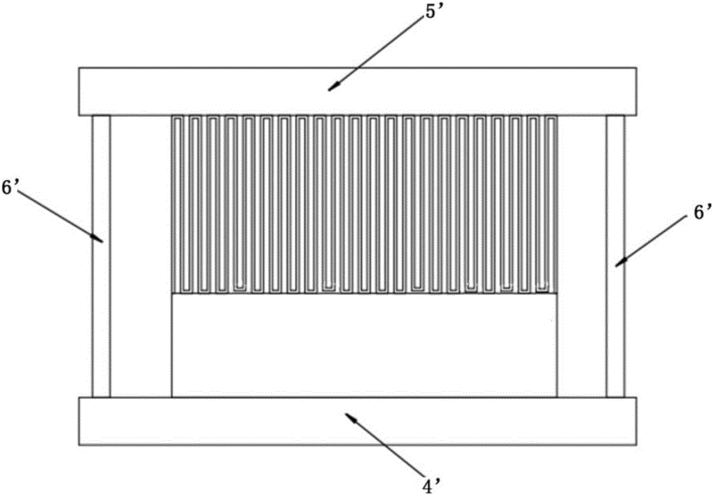
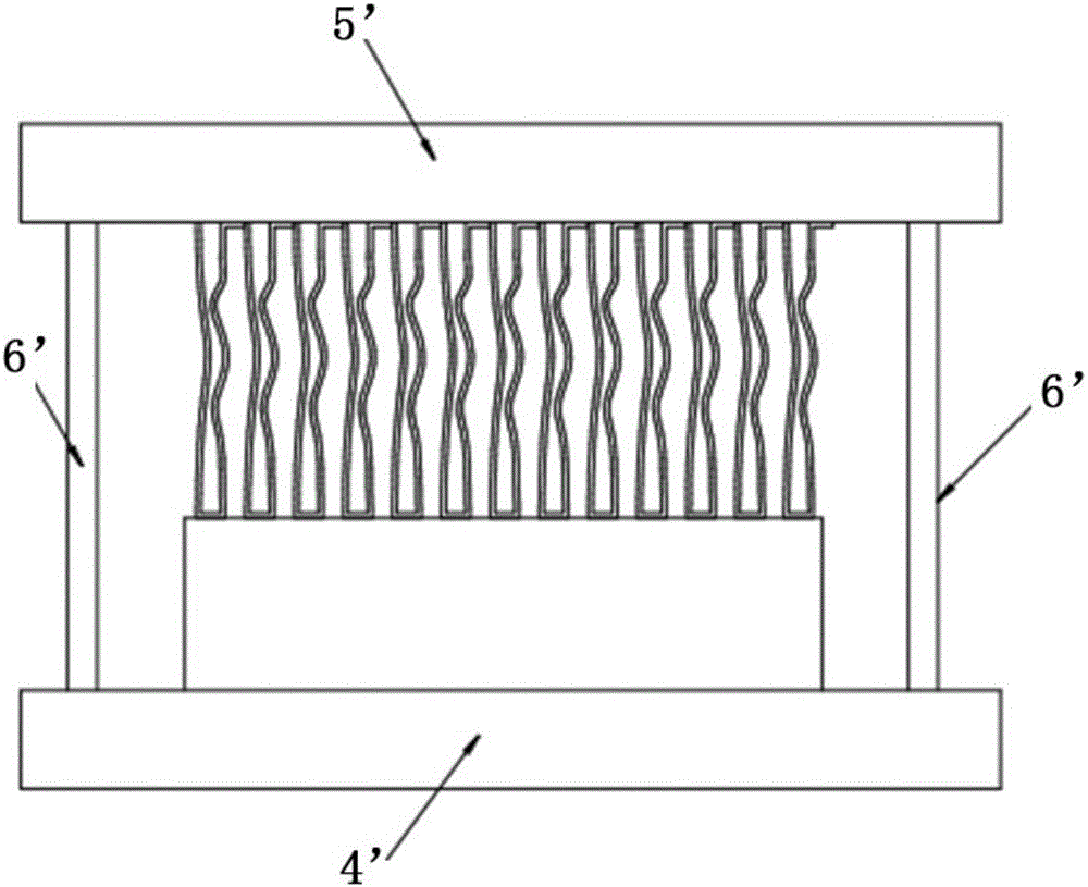
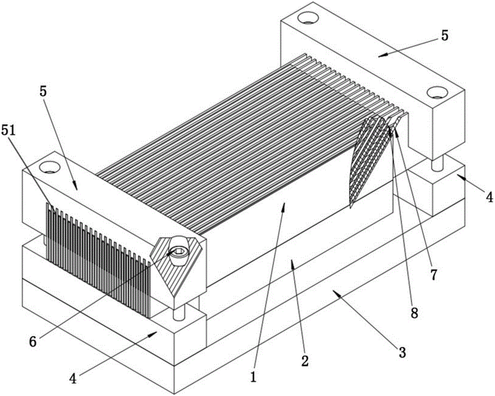
[0020] The welding jig for vacuum brazing of a metal plate and a metal folded sheet of the present invention is mainly used for a welding structure used for vacuum brazing between a metal folded sheet and a metal plate, and the types of products that can be used are mainly similar to radiators, etc. For the welding of relatively dense heat dissipation fins, more effective welding fixtures are required. Of course, in the implementation process, the metal folding sheets may be continuous metal folding sheets, or may be a structure in which U-shaped metal folding sheets are arranged side by side. The main function of the present invention is to squeeze the welded part of the folded metal sheet through the full length of the pressure...


PUM


Abstract

The invention discloses a welding jig for vacuum brazing between a metal plate and a folded metal sheet. The welding jig comprises a base plate, pressing plate limiting blocks, pressing plate positioning blocks and pressing plates, wherein the two pressing plate limiting blocks are arranged on the two sides of the upper surface of the base plate respectively, a space used for containing the metal plate is formed between the two pressing plate limiting blocks, and the folded metal sheet is placed on the upper surface of the metal plate; each pressing plate is arranged between every two adjacent fins of the folded metal sheet in an inserted manner, the bottom surface of each pressing plate abuts against the upper surface of the connected parts of the bottoms of the two corresponding fins in a pressing manner, the length of each pressing plate is larger than that of the folded metal sheet, the two ends of each pressing plate both protrude out of the two sides of the folded metal plate, and the bottom surface of each pressing plate abuts against the upper surfaces of the pressing plate limiting blocks; and the two pressing plate positioning blocks are arranged above the two pressing plate limiting blocks respectively, and are connected with the two pressing plate limiting blocks through locking bolts respectively, so that the two ends of each pressing plate are tightly pressed between the pressing plate positioning blocks and the pressing plate limiting blocks. With the welding jig for vacuum brazing between the metal plate and the folded metal sheet, the welding quality of vacuum brazing between the folded metal sheet and the metal plate can be improved, and the folded metal sheet is prevented from deforming.

Description

technical field [0001] The invention relates to a welding jig, in particular to a welding jig for vacuum brazing a metal plate and a metal folding sheet for vacuum brazing a metal plate and a metal folding sheet. Background technique [0002] In the general process of welding a folded metal sheet to a metal body, due to the thin thickness of the metal sheet, the distance between the folded sheet and the small welding contact area, it is often easy to produce false welding or damage the folded metal sheet. situation arises. In order to improve the welding quality, vacuum brazing is used on the market to weld similar products; this processing method is to press the metal folded sheet on the metal plates that need to be welded together by clamps, and paint on the contact surface Covered with solder, put it into a vacuum brazing furnace for high-temperature welding. Although the products welded in this way have better welding quality and strength than the ordinary welding of th...

Claims


Application Information

Patent Timeline
Patent Type & Authority Applications(China)
IPC IPC(8): B23K3/08B23K1/008
CPCB23K1/008B23K3/087
Inventor 陈基明
Owner 深圳市晟达真空钎焊技术有限公司
Why Eureka
Try Eureka