Wide plastic film winding and roll changing equipment and method for mandrel-free center winding mode
A technology of plastic film and mandrel, applied in the direction of winding strip, thin material processing, transportation and packaging, etc., can solve the problems of increased centrifugal force, deformation of film roll, affecting the compactness of film roll, etc., and achieves low component weight. Effect
- Summary
- Abstract
- Description
- Claims
- Application Information
AI Technical Summary
Problems solved by technology
Method used
Image
Examples
Embodiment 1
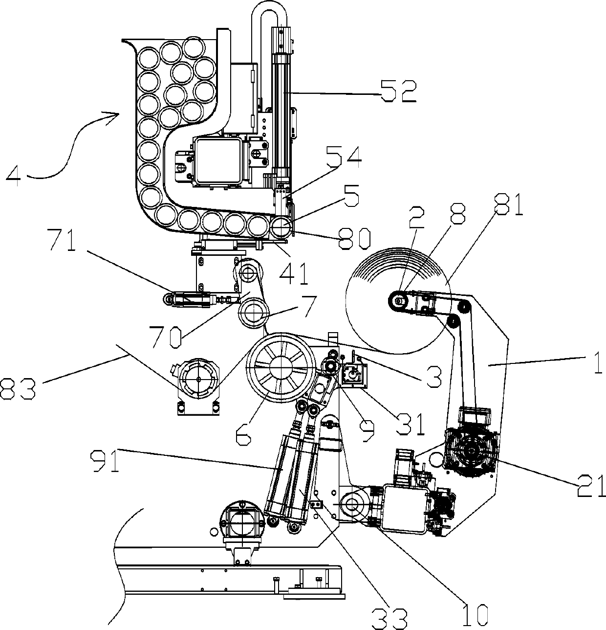
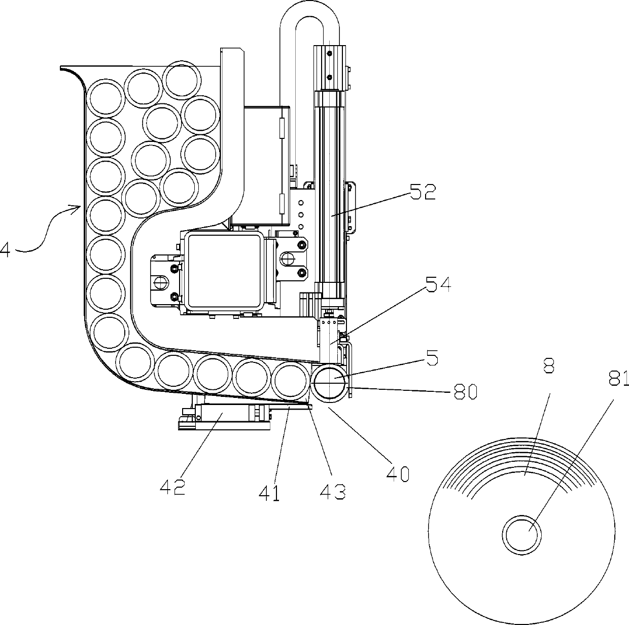
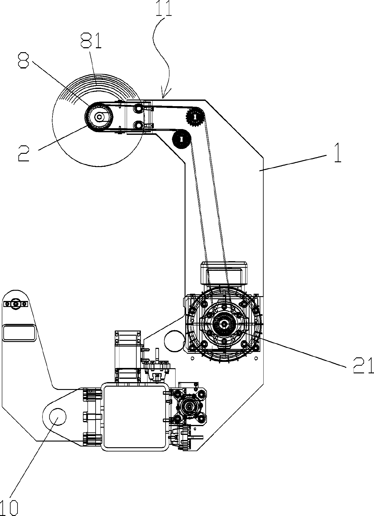
[0043] figure 1 , figure 2 , image 3 , Figure 4 , Figure 5 The wide-width plastic film rewinding and changing equipment shown in the central rewinding mode without a mandrel includes a frame on which two front and rear swing arms 1 that swing synchronously are installed, and the swing arms 1 of the front and rear swing arms 1 The extension direction of the shaft 10 is longitudinal, the swing shafts 10 of the two swing arms are located at the lower end of the swing arm 1, the upper end of the swing arm 1 is formed with a bending section 11 bent to the left, and a main retractor is installed at the end of the bending section 11. Rolling chuck 2, the main winding chuck 2 is an air expansion chuck, the central axis of the main winding chuck 2 is longitudinal, and each swing arm 1 is also equipped with a main winding that drives the main winding chuck 2 to rotate Motor 21, the first longitudinal drive mechanism that drives the main winding chuck 2 to move longitudinally, th...
Embodiment 2
[0051] A wide-width plastic film rewinding and rewinding method without a mandrel center rewinding method, the above-mentioned embodiment 1 is suitable for the wide-width plastic film rewinding and rewinding device without a mandrel center rewinding method, and includes the following steps in sequence:
[0052](1) During normal rewinding, the right idler bracket 90 is located at the lower end of its swing track, the cutter bracket 31 is located at the lower end of its moving track, the preliminary winding support 54 is located at the uppermost end of its moving track, and the gate block 41 It is located directly below the outlet 40 of the storage core chamber and the outlet of the storage core chamber is closed, so that all paper core tubes (including the bottommost paper core tube 80 ) in the storage core cavity cannot fall, such as figure 1 As shown; during normal winding, the friction roller 6 keeps rotating, the front and rear swing arms 1 are in the middle section of their...
PUM
| Property | Measurement | Unit |
|---|---|---|
| thickness | aaaaa | aaaaa |
| diameter | aaaaa | aaaaa |
Abstract
Description
Claims
Application Information
 - R&D
- Intellectual Property
- Life Sciences
- Materials
- Tech Scout
- Unparalleled Data Quality
- Higher Quality Content
- 60% Fewer Hallucinations
Browse by: Latest US Patents, China's latest patents, Technical Efficacy Thesaurus, Application Domain, Technology Topic, Popular Technical Reports.
© 2025 PatSnap. All rights reserved.Legal|Privacy policy|Modern Slavery Act Transparency Statement|Sitemap|About US| Contact US: help@patsnap.com


