
Multi-power-source vehicle driving method and system involved with reusable power generation system

A power generation system, source-driven technology, which is applied in the use of engine-driven traction, the arrangement of multiple different prime movers of general power plants, and electric vehicles, etc. Problems such as long battery charging time

Inactive Publication Date: 2016-12-14
DONGFENG MOTOR CORP HUBEI
View PDF7 Cites 1 Cited by
  • Summary
  • Abstract
  • Description
  • Claims
  • Application Information

AI Technical Summary

Problems solved by technology

[0004] Although the above-mentioned engine + electric drive device realizes the independent drive of multiple power sources, the electric drive part uses the power battery as the power source.
There are the following problems with the power battery as the driving power supply: 1. The poor endurance of the power battery is a common defect at present; 2. The charging time of the power battery is long, and even with the fast charging technology now, it still cannot meet the demand; 3. More critical The most important thing is that there is no perfect charging system in cities and villages, which makes it difficult to widely use vehicles powered by power batteries, especially in areas where there is no power supply in the wild such as grasslands, deserts and mountainous areas. The above-mentioned electric drive devices cannot be realized at all; 4. The electric drive structure cannot meet the needs of the electric load on the vehicle with high power on-board

Method used


Image

  • Multi-power-source vehicle driving method and system involved with reusable power generation system
  • Multi-power-source vehicle driving method and system involved with reusable power generation system
  • Multi-power-source vehicle driving method and system involved with reusable power generation system

Examples


Embodiment 1

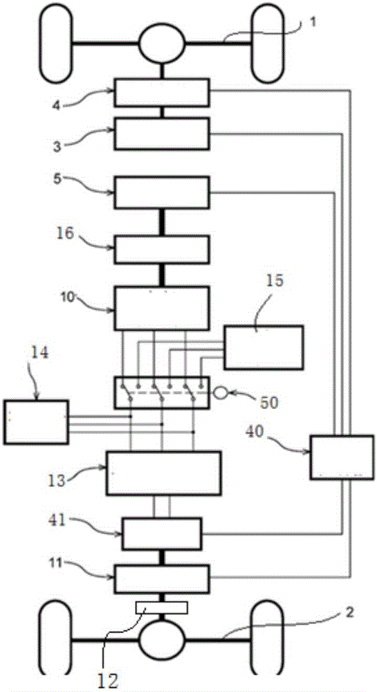
[0033] Such as figure 1 As shown, the first internal combustion engine 3 is arranged on the first axle and the transmission structure 1 on the axle is arranged on the vehicle frame close to the first axle and the transmission structure 1 on the axle. The power output of the first internal combustion engine 3 is connected to the transmission device 4, the transmission device 4 includes a gearbox, and the power output of the transmission device 4 is connected to the transmission structure on the axle. In this way the first internal combustion engine 3 can directly drive the first axle. Of course, a clutch can be set between the first internal combustion engine 3 and the gearbox, or between the gearbox and the transmission structure on the vehicle axle according to requirements.

[0034] The drive motor 11 is arranged on the vehicle frame close to the second axle and the transmission structure 2 on the axle. The power output of the second internal combustion engine 5 is connect...

Embodiment 2

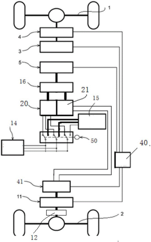
[0036] Such as figure 2 As shown, the first internal combustion engine 3 is arranged on the first axle and the transmission structure 1 on the axle is arranged on the vehicle frame close to the first axle and the transmission structure 1 on the axle. The power output of the first internal combustion engine 3 is connected to the transmission device 4, the transmission device 4 includes a gearbox, and the power output of the transmission device 4 is connected to the transmission structure on the axle. In this way the first internal combustion engine 3 can directly drive the first axle. Of course, a clutch can be set between the first internal combustion engine 3 and the gearbox, or between the gearbox and the transmission structure on the vehicle axle according to requirements.

[0037] The drive motor 11 is arranged on the vehicle frame close to the second axle and the transmission structure 2 on the axle. The power output of the second internal combustion engine 5 is connec...

Embodiment 3

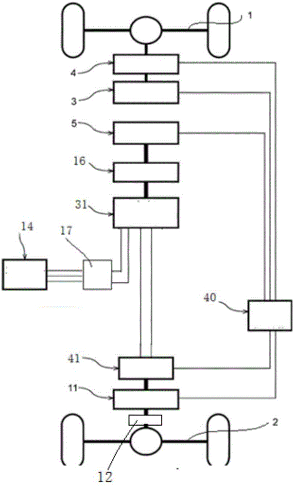
[0039] Such as image 3 As shown, the first internal combustion engine 3 is arranged on the first axle and the transmission structure 1 on the axle is arranged on the vehicle frame close to the first axle and the transmission structure 1 on the axle. The power output of the first internal combustion engine 3 is connected to the transmission device 4, the transmission device 4 includes a gearbox, and the power output of the transmission device 4 is connected to the transmission structure on the axle. In this way the first internal combustion engine 3 can directly drive the first axle. Of course, a clutch can be set between the first internal combustion engine 3 and the gearbox, or between the gearbox and the transmission structure on the vehicle axle according to requirements.

[0040] The drive motor 11 is arranged on the vehicle frame close to the second axle and the transmission structure 2 on the axle. The power of the second internal combustion engine 5 is output and con...


PUM


Abstract

The invention discloses a multi-power-source vehicle driving method and system involved with a reusable power generation system. The driving system at least comprises two axles and a first internal combustion engine, wherein the power output of the first internal combustion engine is connected with a first transmission device, and the power output of the first transmission device is connected to the first axle; the power output of a second internal combustion engine is connected to a power generation device, the output of the power generation device is connected with a driving motor through a cable, and the power output of the driving motor is connected to the second axle or a wheel; the output of the power generation device is connected with a vehicle installation electrical load through a cable. The driving system can especially meet the requirement for providing sufficient power for vehicles traveling in outdoor areas such as grassland, desert and mountain, so that quick maneuverability and long endurance are achieved. The requirement for high-power installation electrical loads is met. Electric energy generated by the vehicle mounted power generator can be reused, and medium-and-high-power generation reuse is achieved especially. The ground clearance of vehicles is reduced, and then vehicle height is reduced so that other transportation tools or devices can be loaded conveniently.

Description

technical field [0001] The invention belongs to the technical field of automobile power, and in particular relates to a multi-power source driving technology for automobiles. Background technique [0002] Vehicle multi-axle drive technology has been widely used in vehicle drive. The traditional use of internal combustion engines to realize multi-axle drive has better power output and good battery life, and is suitable for long-term driving in complex road conditions in the wild. However, the power of the above-mentioned multi-axle-driven vehicle is transmitted to each axle by the internal combustion engine through the transmission shaft system. The transmission shaft system is arranged under the chassis, so that the ground clearance of the chassis is relatively high. height, which limits the carrying capacity of the vehicle. [0003] Existing multi-power source drive technology is applied to vehicles, such as CN200910040759.1, which includes an engine installed on the fron...

Claims


Application Information

Patent Timeline
IPC IPC(8): B60L11/14B60K6/48B60K6/52B60L50/16
CPCB60K6/48B60K6/52B60L50/16Y02T10/62
Inventor 马良杰樊愉杨昌文呼其图陈建贤
Owner DONGFENG MOTOR CORP HUBEI
Learn More