
Method of reducing salt coagulation and corrosion in top reflux system of steam stripping column in hydrogenation apparatus

A technology of a hydrogenation device and a stripper, which is applied in chemical instruments and methods, separation methods, and gas mixture processing, etc., can solve the problem of aggravating the degree of oil-water emulsification in the reflux tank, the unsatisfactory effect of the corrosion inhibitor, and the price of the corrosion inhibitor. expensive, etc.

Active Publication Date: 2016-12-14
EAST CHINA UNIV OF SCI & TECH
View PDF7 Cites 2 Cited by
  • Summary
  • Abstract
  • Description
  • Claims
  • Application Information

AI Technical Summary

Problems solved by technology

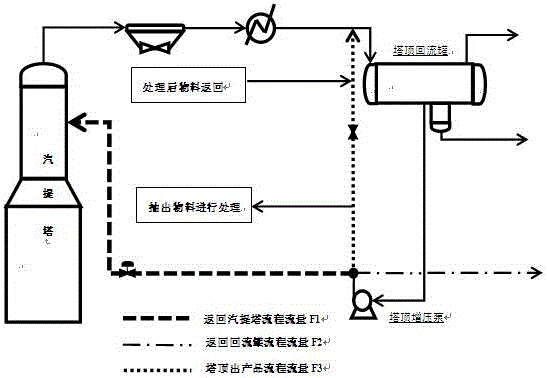
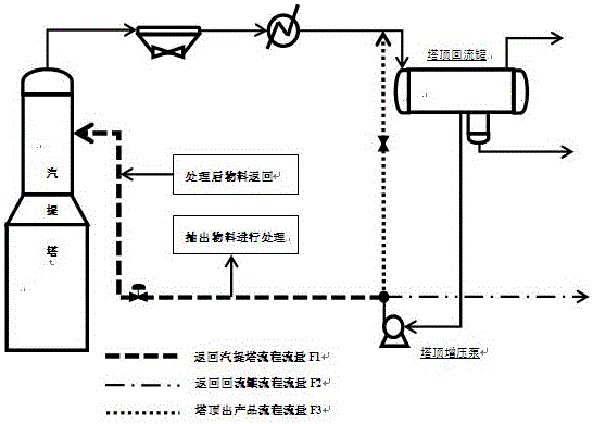
[0007] The flow rate of the material returned to the reflux tank after the booster pump of the reflux tank is 5~10t / h, accounting for about 25%~50% (w / w) of the total amount extracted from the top of the stripping tower, and the material returned to the reflux tank at the top of the tower can be very It is convenient to adjust the flow rate of the material out of the device after the return booster pump through the bypass, but it intensifies the degree of oil-water emulsification in the return tank, making the oil-water separation effect of the return tank worse
[0008] For the desalination and anti-corrosion of the top system of most residual oil hydrogenation strippers, in order to reduce the corrosion of the top pipes and heat exchangers, the traditional method generally uses corrosion inhibitors to inject corrosion inhibitors into the top pipes of the stripper. The price of the corrosion inhibitor is expensive, and the effect of the corrosion inhibitor is not satisfactory in the fractionation tower of some hydrogenation units
[0009] And because there is a certain amount of solid impurities in the top reflux of the residual oil hydrogenation stripping tower, it is difficult to achieve long-term dehydration by the commonly used method of injecting water at the tower feed.

Method used


Image

  • Method of reducing salt coagulation and corrosion in top reflux system of steam stripping column in hydrogenation apparatus
  • Method of reducing salt coagulation and corrosion in top reflux system of steam stripping column in hydrogenation apparatus
  • Method of reducing salt coagulation and corrosion in top reflux system of steam stripping column in hydrogenation apparatus

Examples


Embodiment

[0037] Due to the existence of sulfur, chlorine and other impurities in the feed oil of a petrochemical 3 million tons / year residual oil unit, the salt content of the circulating oil system at the top of the stripping tower is too high. With the increase of operating time, the salt content The crystallization of more salts will block the trays, air cooling, circulation pumps and pipelines, which will increase the possibility of flushing the tower, and the crystallization particles will increase the erosion and wear of the equipment, endangering safe production and increasing the difficulty of operation. At the same time, corrosion occurs in air cooling, heat exchangers, booster pumps, pipelines, etc. in the stripping tower top reflux system. The oil salt content of the top reflux of the stripper was measured to be about 6 mg / L.

[0038] In order to reduce the corrosion of the tower top pipe and heat exchanger, the device uses intermittent water injection on the pipeline flow b...


PUM


Abstract

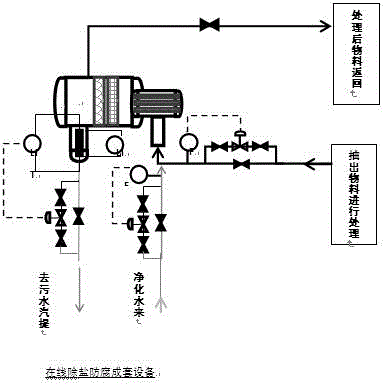
The invention relates to a method of reducing salt coagulation and corrosion in a top reflux system of a steam stripping column in a hydrogenation apparatus. A sub-line extraction process is added on the basis of a top reflux process of the steam stripping column and includes a water injection device, a secondary extractor and a long-period dehydrator. Oil phase discharged from a reflux tank passes through a reflux tank pressurizing pump and then is divided into three pipelines, wherein the first one is fed back to the steam stripping column, the second one is discharged from the apparatus and the third one is fed back to the top reflux tank. The method achieves long-period stable operation of the hydrogenation apparatus.

Description

technical field [0001] The present invention relates to a method for reducing salt formation and corrosion in the stripping tower top reflux system of a hydrogenation unit, in particular to a stripping tower top reflux system with serious corrosion and salt formation in a residual oil hydrogenation unit. The method of salt accumulation and corrosion, and the similar transformation of similar towers of similar hydrogenation units, realize the long-term stable operation of hydrogenation units. Background technique [0002] Hydrogenation of residual oil is a method to deal with residual oil with high salt content and high metal content. Due to the inferior quality of raw materials for hydrogenation of residual oil, the corrosion and salt formation of the residual oil hydrogenation unit are serious, especially in the residual oil hydrogenation unit. There are serious problems of ammonium salt clogging and equipment corrosion at the top of the column. [0003] The hot low-fracti...

Claims


Application Information

Patent Timeline
Patent Type & Authority Applications(China)
IPC IPC(8): C10G70/06B01D3/00B01D3/42
CPCB01D3/00B01D3/42C10G70/06C10G2300/4081
Inventor 杨强许萧卢浩竺嘉斌刘懿谦
Owner EAST CHINA UNIV OF SCI & TECH
Learn More