
Side-tracking slim hole layered fracturing string and side-tracking slim hole layered fracturing method

A technology of layered fracturing and side-drilling, which is applied in wellbore/well components, earth-moving drilling and production of fluids, etc., can solve the problems of incomplete fracturing stimulation, unreliable stratification, and no field application.

Active Publication Date: 2016-12-14
BC P INC CHINA NAT PETROLEUM CORP +1
View PDF1 Cites 21 Cited by
  • Summary
  • Abstract
  • Description
  • Claims
  • Application Information

AI Technical Summary

Problems solved by technology

Another possible method for slim hole layered fracturing is hydraulic jet layered fracturing. The oil casing injection method can appropriately increase the fracturing displacement. However, the minimum outer diameter of the injector is Φ80mm at present, and Φ70mm is not seen. Application reports for the following injectors
There is another possible method for layered fracturing of slim holes is to use cementing sleeves for layered fracturing. This method has been used in several wells in conventional wells, but the failure rate is quite high. Sliding sleeve fracturing in layers may have a higher failure rate, so far no field application has been seen
Other slim hole layered fracturing methods such as current limiting method and temporary plugging method are not effective isolation layering techniques, the layering is unreliable, and the fracturing stimulation is not thorough

Method used


Image

  • Side-tracking slim hole layered fracturing string and side-tracking slim hole layered fracturing method
  • Side-tracking slim hole layered fracturing string and side-tracking slim hole layered fracturing method

Examples


Embodiment 1

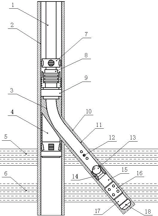
[0030] This embodiment provides a sidetracking slim hole layered fracturing string, including a casing 2, a first tubing 1, a tubing anchor 7, and a fracturing plug 8 arranged in the casing 2 and connected sequentially from top to bottom, As well as the liner string, there is a lateral borehole on the casing 2, the upper end of the liner string is connected to the fracturing plug 8, and the lower end passes through the lateral borehole;

[0031] The liner string is composed of a hanger 9, a second oil pipe 3, a ball seat 14, a third oil pipe 15, a soluble eye pipe 16, a fourth oil pipe 17, and a liner shoe 18 connected sequentially from top to bottom. The hanger 9 is connected to the fracturing plug 8 .

[0032] The working process of this embodiment takes a slim hole of Φ118mm drilled inside the original wellbore of Φ124mm as an example: figure 1 As shown, a skewer 4 is lowered into the casing 2, and the skewer 4 is locked on the inner wall of the casing 2. Through the skewe...

Embodiment 2

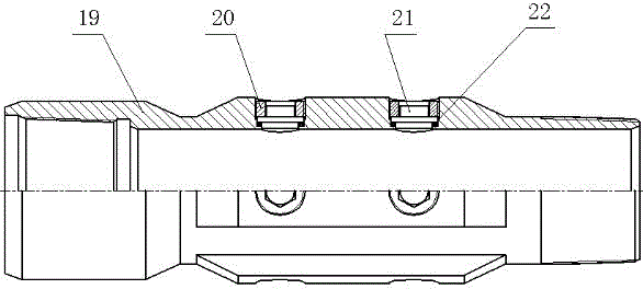
[0035] On the basis of Embodiment 1, this embodiment provides a sidetracking slim hole layered fracturing string, the soluble hole pipe 16 includes a body 19, and the body 19 is provided with a plurality of radial holes, Sealing ring 22, soluble plug 21, nut 20 are all housed in each radial hole, and described nut 20 is threadedly connected with body 19, and sealing ring 22 is pressed tightly on the body 19 by soluble plug 21 On the step inside the radial hole. like figure 2 shown.

[0036] In this embodiment, the fracturing plug 8 is a compression packer, and the fracturing plug 8 is inserted into the stepped hole of the hanger 9 . The compression packer can seal a large annular gap by using the large expansion rate performance of the compression rubber cartridge, and has a high pressure bearing capacity.

[0037] Wherein, the outer surface of the main body 19 has longitudinal guide grooves. The diversion groove can ensure the smooth flow of cement 11 during well cementi...

Embodiment 3

[0039] This embodiment provides a layered fracturing method for a sidetracked slim hole. A sidetracked wellbore 10 is drilled inside the original wellbore, a liner string is lowered into the sidetracked wellbore 10, and the liner string is cemented. Finally, the fracturing channel of the lower reservoir 6 is opened, and the fracturing operation of the lower reservoir 6 is carried out after the tailpipe string is connected with the wellhead tool string; the upper reservoir 5 is perforated, and then isolated from the lower reservoir 6, and the upper reservoir 5 Carry out fracturing construction.

[0040] The fracturing method does not need to run in fracturing tools, which not only meets the construction requirements of large displacement fracturing, but also avoids the risk of running in downhole tools.

[0041] Example 3:

[0042] On the basis of Embodiment 1 or Embodiment 2, this embodiment provides a layered fracturing method for a sidetracked slim hole, in which a sidetrac...


PUM


Abstract

The invention provides a side-tracking slim hole layered fracturing string which comprises a sleeve, a first oil pipe, a tubing anchor, a fracturing plug and a tail string, wherein the first oil pipe, the tubing anchor, the fracturing plug and the tail string are arranged in the sleeve and are sequentially connected from top to bottom; the sleeve is provided with a flank hole; the upper end of the tail string is connected with the fracturing plug, and the lower end of the tail string passes through the flank hole; the tail string consists of a hanger, a second oil pipe, a ball seat, a third oil pipe, a soluble porous pipe, a fourth oil pipe and a tail pipe shoe which are sequentially connected from top to bottom; the hanger is connected with the fracturing plug. The invention also provides a fracturing method. A fracturing tool is not needed to be fed, not only can the large-displacement fracturing construction requirement be met, but also downhole tool feeding risks can be avoided, and meanwhile perforating operation at a lower reservoir stratum is omitted; compared with a well cementation sliding sleeve layered fracturing method, the risk that the sliding sleeve cannot be opened is avoided, furthermore, the side-tracking slim hole layered fracturing method has the characteristics that the blank of layered fracturing technology in feeding tail strings with an inner diameter of 76mm into a slim hole with an inner diameter of 118mm and cementing the well by using cement is filled.

Description

technical field [0001] The invention belongs to the technical field of layered fracturing of oil and gas wells, and in particular relates to a sidetracking slim hole layered fracturing string and a method. Background technique [0002] At present, most major oil fields at home and abroad have entered the middle and late stages of development, and the production capacity of oil and gas wells decays rapidly. When the production is too low, they no longer have the value of exploitation. In order to save costs, the technology of drilling slim holes inside old wells has been developed rapidly, especially in offshore platforms and mountain oilfields. Sidetracking of old wells not only avoids costly well site construction, but also reduces pipeline network construction and environmental pollution. This is of great significance to today's oil and gas field enterprises with the theme of energy conservation and environmental protection. For the larger original wellbore, the sidetrack...

Claims


Application Information

Patent Timeline
IPC IPC(8): E21B43/26E21B29/06E21B23/00E21B33/13E21B33/127
CPCE21B23/00E21B29/06E21B33/127E21B33/13E21B43/26
Inventor 宋振云张承武王兴建吴增智李志航王惠生王玉功李雪
Owner BC P INC CHINA NAT PETROLEUM CORP
Learn More