Energy storage device

An energy storage device and power storage technology, applied in elastic engines, machines/engines, mechanical equipment, etc., can solve the problems of volume, weight, cost, process, and safety constraints of energy storage devices, and achieve light weight, low cost, easy to achieve effect

Active Publication Date: 2016-12-14
NANTONG HONGFENG ELECTRO MECHANIC
View PDF9 Cites 8 Cited by
  • Summary
  • Abstract
  • Description
  • Claims
  • Application Information

AI Technical Summary

Problems solved by technology

[0002] Elastic metal energy storage devices are generally used as power for micro-machines without the use of electric energy. Because the kinetic energy is limited, they can only be used in some small power devices. If you want to provide greater kinetic energy, only By increasing the thickness, width or length of the elastic metal, the advantages of the volume, weight, cost, process, safety, etc. of the energy storage device will be restricted

Method used


Image

  • Energy storage device
  • Energy storage device
  • Energy storage device

Examples


Embodiment approach

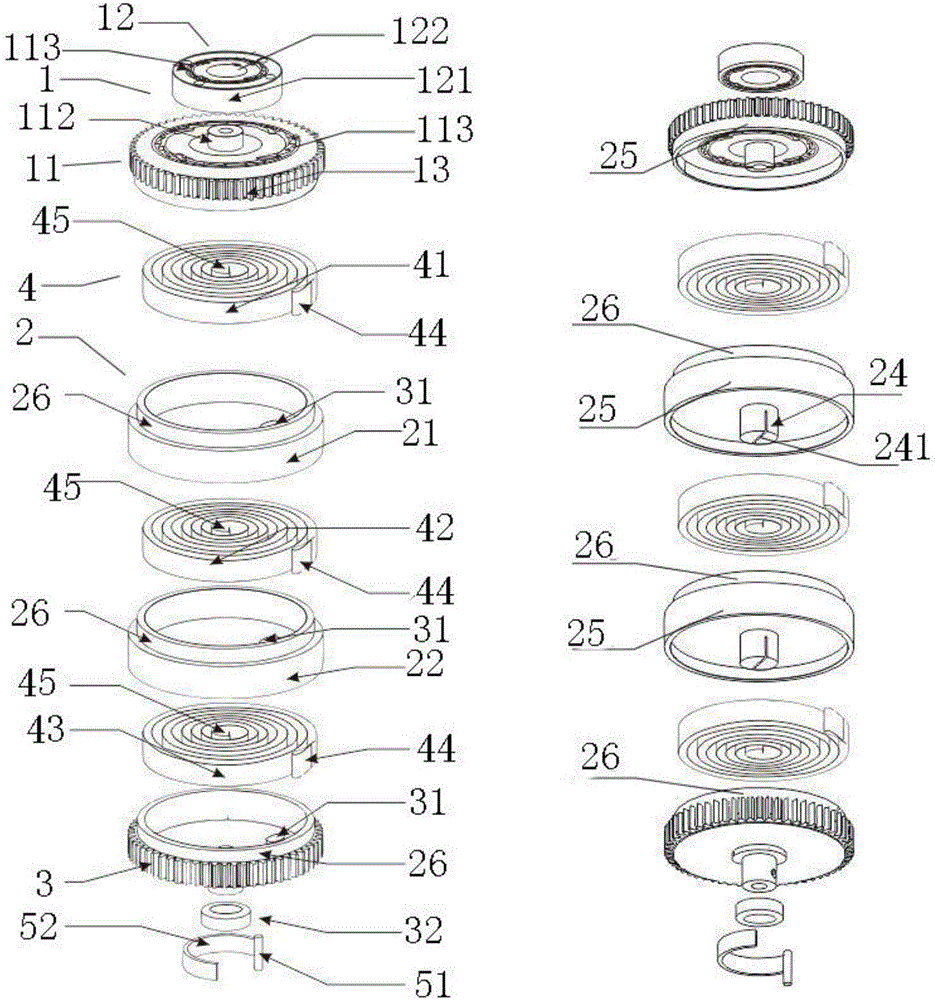
[0054] The power storage connecting plate assembly 2 of this embodiment has two implementation modes, specifically as follows:

Embodiment approach 1

[0055] Embodiment 1: The power storage connection plate assembly 2 includes a connection plate, and the power storage elastic piece assembly 4 includes a power storage elastic piece; one end surface of the connection plate is rotatably connected to one end surface of the power storage assembly 1 , the other end of the connection plate is rotatably connected to one end of the release gear 3, there is a gap between the connection plate and the release gear 3, and the power storage shrapnel is fixedly installed in the gap. In this embodiment, the energy storage function can be realized through a connection plate and a force storage shrapnel.

Embodiment approach 2

[0056] Embodiment 2: The power storage connecting disc assembly 2 includes a plurality of connecting discs which are sequentially rotated and connected, and the power storage shrapnel assembly 4 includes a plurality of power storage shrapnels for converting the kinetic energy of the power storage assembly 1 into its own elastic force; There is a gap between two adjacent connection plates; in this embodiment, multiple connection plates and multiple power storage shrapnels can be provided to realize multi-stage force storage.

[0057] The plurality of connection plates are respectively the first connection plate 21, the second connection plate 22, ..., the n-1th connection plate and the nth connection plate, which are sequentially rotated and connected. Force shrapnel 41, the second power storage shrapnel 42, the third power storage shrapnel 43, ..., the n-2th power storage shrapnel and the n-1th power storage shrapnel;

[0058] One end face of the first connecting plate 21 is r...


PUM


Abstract

The invention relates to an energy storage device which comprises an energy storage assembly, an energy storage connecting disc assembly, a release gear, an energy storage elastic plate assembly and an energy storage release switch, wherein the energy storage assembly and the energy storage connecting disc assembly are cylindrical; one end surface of the energy storage connecting disc assembly is rotationally connected onto one end surface of the energy storage assembly; the release gear is round; the other end of the energy storage connecting disc assembly is rotationally connected onto one end surface of the release gear; the energy storage elastic plate assembly is used for converting kinetic energy of the energy storage assembly into own elastic force, and fixedly mounted in the energy storage connecting disc assembly or between the energy storage connecting disc assembly and the release gear; and the energy storage release switch is used for fixing or rotating the release gear and fixedly connected with the release gear. The energy storage device provided by the invention has the advantages that through arrangement of the energy storage assembly, the energy storage connecting disc assembly, the release gear and the energy storage elastic plate assembly, the energy storage assembly can be rotated, the kinetic energy of the energy storage assembly can be converted by the energy storage elastic plate assembly into the own elastic force of the energy storage elastic plate assembly, and then energy storage can be achieved. Accordingly, the whole energy storage process is simple and easy to achieve.

Description

technical field [0001] The invention relates to the technical field of energy utilization, in particular to an energy storage device. Background technique [0002] Elastic metal energy storage devices are generally used as power for micro-machines without the use of electric energy. Because of limited kinetic energy, they can only be used in some small power devices. If you want to provide greater kinetic energy, only By increasing the thickness, width or length of the elastic metal, the advantages of the volume, weight, cost, process and safety of the energy storage device will be restricted. Contents of the invention [0003] The technical problem to be solved by the present invention is to provide an energy storage device for the deficiencies of the prior art. [0004] The technical solution of the present invention to solve the above-mentioned technical problems is as follows: an energy storage device, comprising: [0005] a power storage component, the power storage...

Claims


Application Information

Patent Timeline
Patent Type & Authority Applications(China)
IPC IPC(8): F03G1/00F03G1/02
CPCF03G1/00F03G1/02
Inventor 王怡科
Owner NANTONG HONGFENG ELECTRO MECHANIC
Why Eureka
Try Eureka