Electric vehicle vacuum pump

A technology for electric vehicles and vacuum pumps, which is applied to pumps, piston pumps, pump components, etc., and can solve problems such as loud noise, easy leakage at the blockage, and changes in concentricity.

Active Publication Date: 2019-01-08
浙江品达机动车部件有限公司
View PDF10 Cites 1 Cited by
  • Summary
  • Abstract
  • Description
  • Claims
  • Application Information

AI Technical Summary

Problems solved by technology

During the assembly process, although the concentricity between the connecting rod and the installation opening of the pump casing is corrected, the special tool will shake the connecting rod when the lock on the clamping piece is locked, which will change the corrected concentricity.
Such a structure and assembly method will cause the piston cup and cup to be subjected to different forces in all directions in the cylinder liner, which will easily lead to increased wear and tear at the place where the force is high, making the product invalid, thus failing to provide a better vacuum boost for the internal system of the car.
Moreover, the installation hole on the pump casing needs to be sealed after the above-mentioned assembly is carried out, and the sealing place is prone to leakage.
[0004] The entry part of the traditional one-way valve is provided with a one-way valve gasket. During the vacuuming process of the electric vacuum pump, the one-way valve gasket will continuously collide with the one-way valve, and a large force will be generated when the collision occurs. noise, a noise reduction valve is usually installed at the exhaust part of the one-way valve, however, the noise reduction valve can only reduce the noise to a certain extent, and does not eliminate the noise from the root
Moreover, the traditional noise reduction valve is a part independently installed on the check valve, so it is difficult to guarantee the uniformity of its processing and products

Method used


Image

  • Electric vehicle vacuum pump
  • Electric vehicle vacuum pump
  • Electric vehicle vacuum pump

Examples


Embodiment Construction

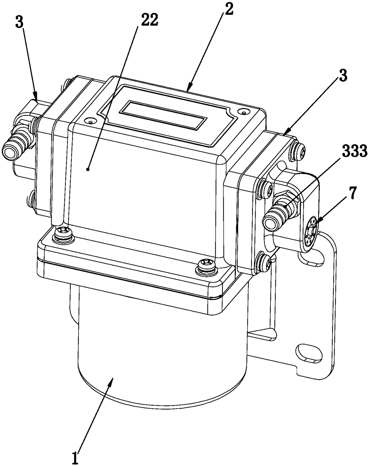
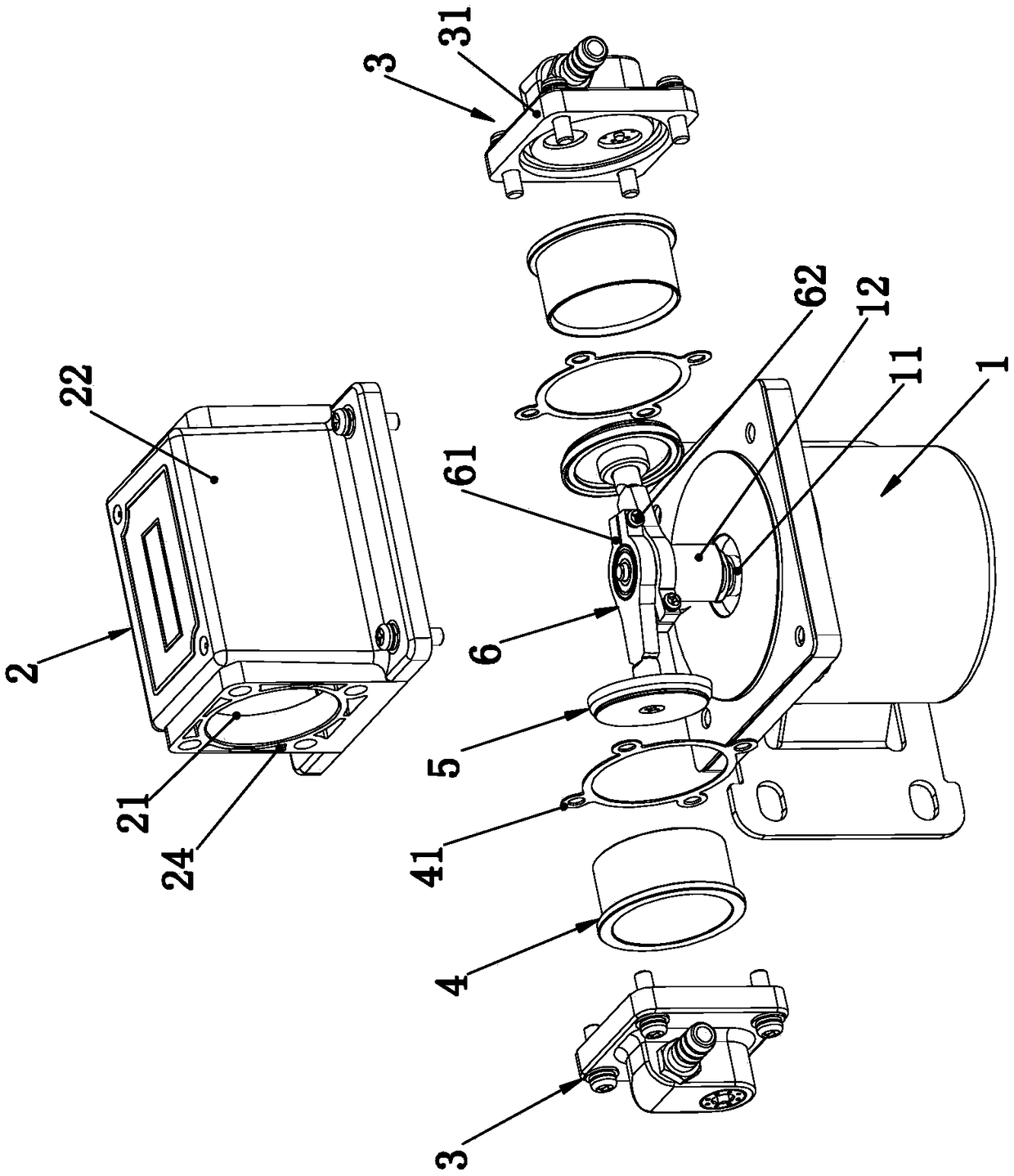
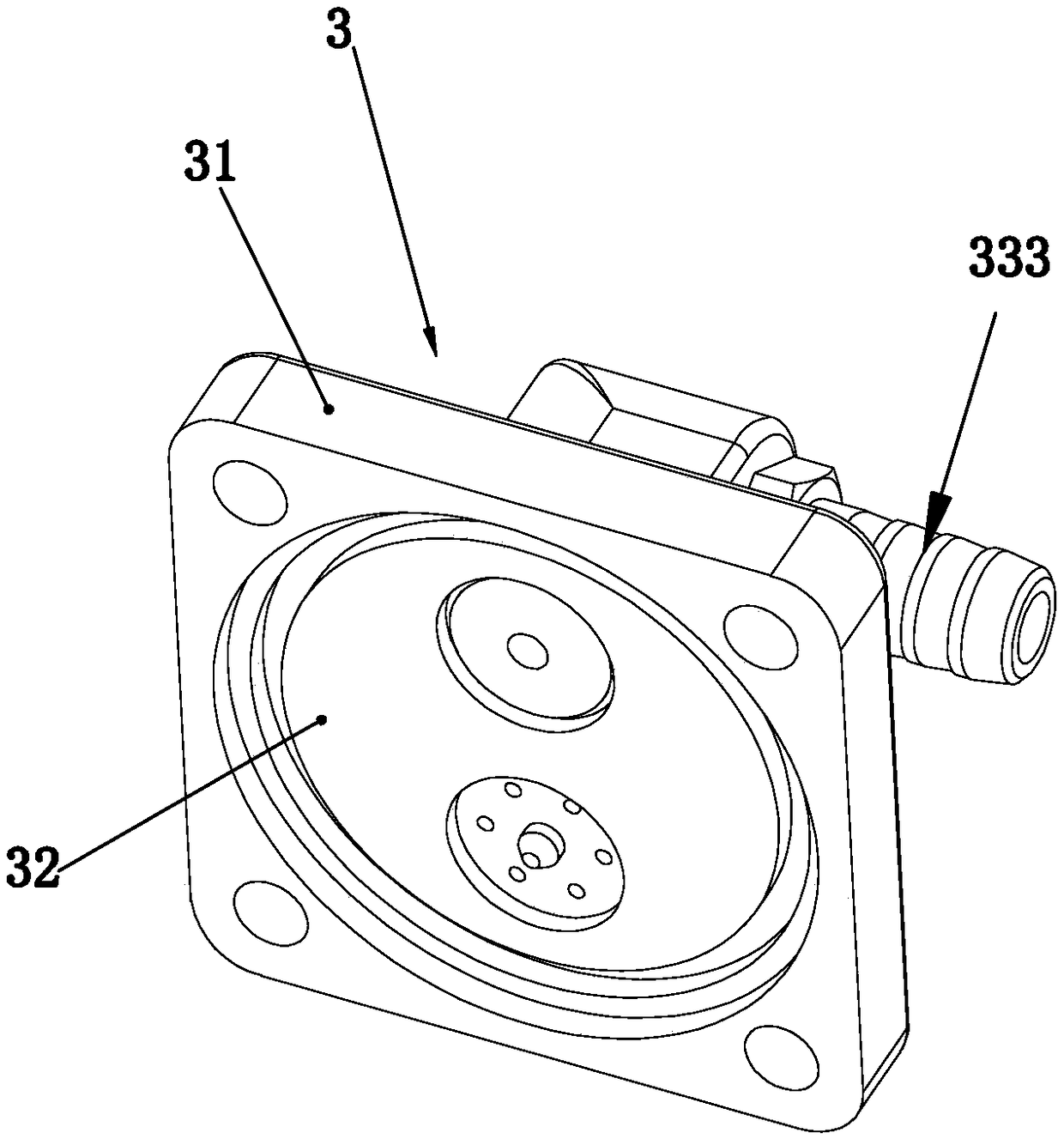
[0025] Such as figure 1 — Figure 7A vacuum pump for electric vehicles shown includes a motor 1, a pump casing 2 erected on the motor 1, an installation opening 21 is provided on the pump casing 2, a check valve 3 and a cylinder liner 4 are arranged at the installation opening 21, and The piston cup 5 that is linked with the motor 1 and can move back and forth in the cylinder liner 4, the piston cup 5 is connected with the motor shaft 11 of the motor 1 through the crankshaft 12 through the connecting rod 6, and the end connecting the connecting rod 6 and the crankshaft 12 has two pieces Open clamping pieces 61 are fixedly connected by fasteners 62 between the two clamping pieces 61, such as screws. The one-way valve 3 includes a one-way valve body 31, which is arranged on the one-way valve body 31 and connected with the cylinder. The connecting chamber 32 connected to the sleeve 4, the air intake passage 33 and the exhaust passage 34 connected with the connecting chamber 32, ...


PUM


Abstract

The invention relates to automobile spare parts, in particular to an electric automobile vacuum pump. The invention has the technical scheme that the electric automobile vacuum pump comprises a motor, a pump shell, installation openings arranged on the pump shell, one-way valves and cylinder sleeves arranged on the installation openings, and piston rubber cups arranged in the cylinder sleeves. The piston rubber cups are connected with a motor shaft of the motor through a connecting rod through a crankshaft; the installation openings are arranged on the two ends in a longitudinal direction of the pump shell; the cylinder sleeves and the one-way valves connected with the pump shell are arranged on the installation openings; the two ends in a transverse direction of the pump shell are sealed end faces; one-way valve sealing gaskets with the peripheral surfaces being sealed with inner walls of air inlet passageways and exhaust passageways are clamped in the air inlet passageways and the exhaust passageways of the one-way valves; and air inlet one-way valve plates and exhaust one-way valve plates are arranged on the one-way valve sealing gaskets. By adopting the technical scheme, the invention provides the electric automobile vacuum pump, which is capable of keeping the concentricity when the connecting rod and the installation openings of the pump shell are assembled, good in sealing performance, reduced in noise, and simple in structure.

Description

technical field [0001] The invention relates to an automobile accessory, in particular to a vacuum pump for an electric automobile. Background technique [0002] The electric vacuum pump is the vacuum source of the automobile vacuum hydraulic brake and booster system. It is mainly composed of a motor, a pump casing erected on the motor, and the longitudinal ends of the pump casing are respectively equipped with installation openings. The two installation openings are respectively equipped with check valves and The cylinder liner, the piston cup that is linked with the motor and can move back and forth in the cylinder liner, the piston cup is connected to the motor shaft of the motor through the connecting rod through the crankshaft, and the end of the connecting rod connected to the crankshaft has two opening-shaped clamps The two clamping pieces are fixed by screws to lock the connecting rod and the crankshaft, and the one-way valve is provided with a pipeline connected wit...

Claims


Application Information

Patent Timeline
Patent Type & Authority Patents(China)
IPC IPC(8): F04B35/04F04B39/10F04B39/12
CPCF04B35/04F04B39/10F04B39/121F04B39/127
Inventor 吴鹏
Owner 浙江品达机动车部件有限公司
Why Eureka
Try Eureka