
A pump body structure capable of improving fluid flow conditions in a vortex pump

A technology of internal fluid and vortex pumps, which is applied to parts of pumping devices for elastic fluids, liquid fuel engines, pumps, etc., and can solve the problem of disordered flow in the outlet cavity, affecting the overall efficiency of the pump, and turbulence in the flow of vortex pumps and other problems, to achieve the effect of being convenient for large-scale application, simple and reasonable structure, and low cost

Active Publication Date: 2018-12-04
ZHEJIANG SINCONTROL PUMP IND
View PDF5 Cites 0 Cited by
  • Summary
  • Abstract
  • Description
  • Claims
  • Application Information

AI Technical Summary

Problems solved by technology

Because of this, the flow inside the vortex pump is turbulent, resulting in low efficiency of the pump
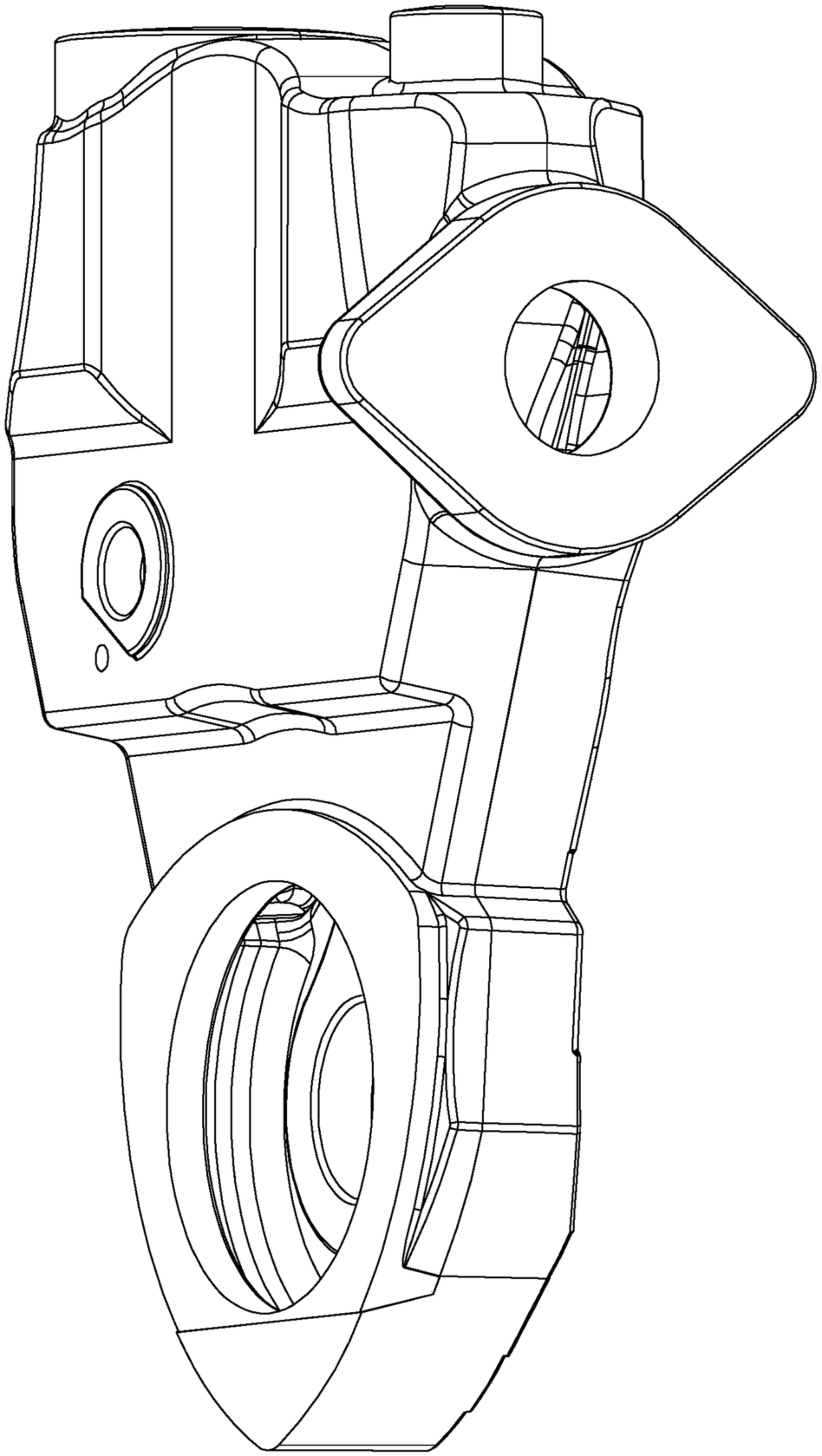
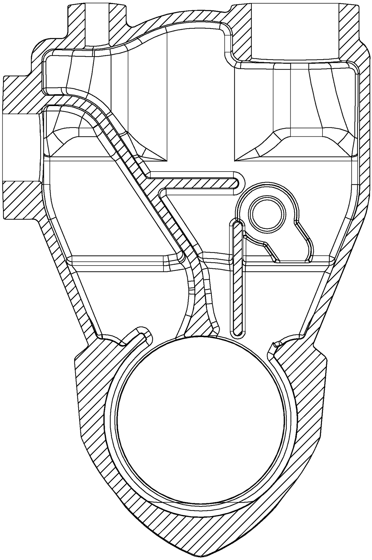
[0003] At present, scholars at home and abroad have done a lot of research and experiments on the design and internal flow of the vortex pump, especially the research on the impeller and the flow channel of the impeller, which occupies the vast majority, while ignoring the inlet volute and outlet volute. The impact on the overall performance of the vortex pump, the existing vortex pumps on the market have many unreasonable places in the design of the inlet volute and the outlet volute, for example, such as figure 1 , 2 As shown, there are generally two horizontal and vertical baffles in the existing vortex pump body, the purpose is to improve the self-priming capacity by strengthening the gas-liquid separation, but the experiment proves that these two baffles do not play the role expected in theory. On the contrary, the flow in the water outlet cavity will be more chaotic and disorderly, and a high-speed vortex will be generated in the area formed by the two baffles and the wall of the pump casing; The right-angle transition section, which will produce backward step backflow and local loss, that is, the step causes flow separation, vortex generation and shedding, interaction between vortexes and between vortex and solid wall, resulting in more fluid flow inside the vortex pump. For disorder, the energy efficiency is low, generally below 40%, which in turn affects the overall efficiency of the pump

Method used


Image

  • A pump body structure capable of improving fluid flow conditions in a vortex pump
  • A pump body structure capable of improving fluid flow conditions in a vortex pump
  • A pump body structure capable of improving fluid flow conditions in a vortex pump

Examples


Embodiment Construction

[0021] The present invention will be further described in detail below in conjunction with the accompanying drawings and embodiments.

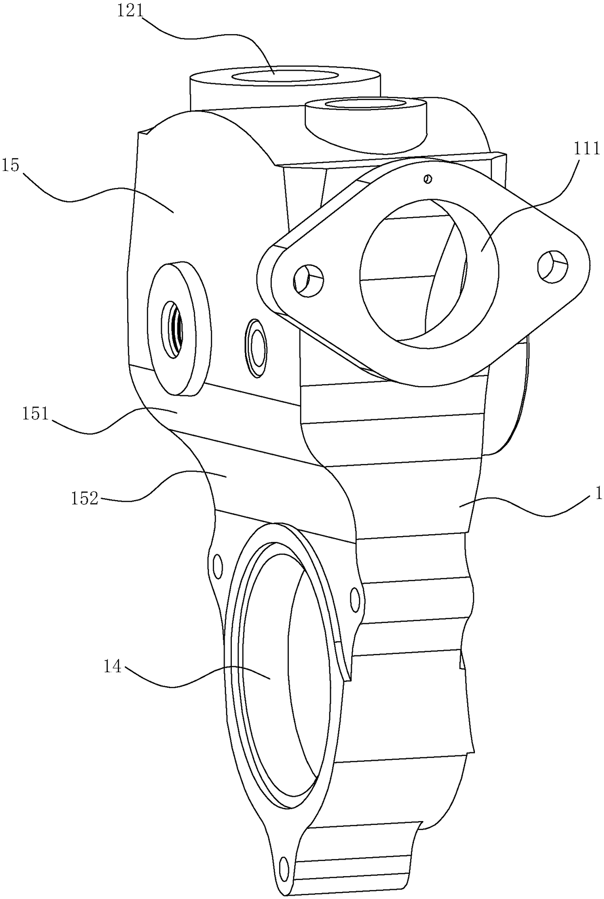
[0022] Such as Figure 3-5 As shown, the pump body structure of this embodiment that can improve the fluid flow in the vortex pump includes a body 1 with an inner cavity 10, and the inner cavity 10 is provided with a water inlet volute chamber 11 and an outlet volute. The partition tongue 13 of the chamber 12, the lower part of the body 1 has a flow channel 14 for installing the impeller which communicates with the water inlet volute 11 and the water outlet volute 12 respectively. One side of the water inlet volute 11 has a water inlet 111, and the water outlet The top of the volute 12 has a water outlet 121 .

[0023] In this embodiment, the upper part of one side of the main body 1 extends outward to form a boss 15 , the bottom edge of the boss 15 is shaped as a first arc surface 151 that arches outward, and the side of the main body 1 at t...


PUM


Abstract

The invention relates to a pump body structure capable of improving the flow state of fluid in a vortex pump. The pump body structure comprises a body, wherein an inner cavity is formed in the body, a baffle tongue which is used for dividing the inner cavity into a water inlet vortex chamber and a water outlet vortex chamber is arranged in the inner cavity, a boss extends outwards from the upper part of one side surface of the body, a first arc surface which is arched outwards is formed at the edge of the bottom of the boss, a second arc surface which is arched inwards is formed on the side surface of the body on the top of a flow channel, the upper edge of the second arc surface is tangentially connected with the lower edge of the first arc surface, and streamline divergent sections which correspond to the first arc surface and the second arc surface are formed on the inner surface of the inner cavity. According to the pump body structure, the lower parts of the water inlet vortex chamber and the water outlet vortex chamber are tangent to an impeller channel, so that backflow and local resistance which are caused by space mutation as well as flow resistance caused by vortexes and flow separation of liquid working media at the boss are reduced, energy loss caused by interaction between vortexes of the liquid working media in the pump or between the vortexes and the wall surface is reduced, and the efficiency of the vortex pump is improved.

Description

technical field [0001] The invention relates to the technical field of vortex pumps, in particular to a pump body structure capable of improving fluid flow conditions in a vortex pump. Background technique [0002] Vortex pumps, also known as friction pumps and regenerative pumps, are general-purpose machines with a large volume and a wide range of energy consumption. They first appeared in the 1920s and were created and promoted by Simon and Hensch. Special vane pumps with vane impellers work almost wherever there is liquid flow. The vortex pump has the characteristics of simple structure and high lift, so it is widely used in various fields of household and national economy. When the vortex pump is working, the liquid flows into the impeller from the suction port, and then flows back to the flow channel after being accelerated by the impeller, and transfers energy to the liquid in the flow channel. After repeating this many times, it flows out from the outlet of the press...

Claims


Application Information

Patent Timeline
Patent Type & Authority Patents(China)
IPC IPC(8): F04D29/42
CPCF04D29/426
Inventor 陈荣国颜正辉陈志平陈海林包福兵凃程旭赵飞
Owner ZHEJIANG SINCONTROL PUMP IND
Learn More