
Built-in displacement sensor integrated single piston rod symmetrical hydraulic cylinder

A technology of displacement sensors and symmetrical hydraulic cylinders, applied in fluid pressure actuators, mechanical equipment, etc., can solve the problems of limited integrated hydraulic cylinders, low degree of integration, and non-integrated systems, and achieve the solution of flow and stability Contradictions, enhanced anti-interference ability, and easy maintenance

Inactive Publication Date: 2016-12-14
TIANJIN UNIV
View PDF11 Cites 6 Cited by
  • Summary
  • Abstract
  • Description
  • Claims
  • Application Information

AI Technical Summary

Problems solved by technology

At present, the research on integrated hydraulic cylinders is relatively limited, and the low degree of integration is a common problem. How to arrange the motor, oil pump, valve block, pipeline and hydraulic cylinder in a reasonable space is the primary problem; and about symmetrical hydraulic cylinders The biggest problem is that the spatial relationship between the displacement sensor and the hydraulic cylinder cannot be properly arranged. In order to ensure the working performance of the symmetrical hydraulic cylinder, the displacement sensor can only be placed outside the cylinder or the magnetic ring of the displacement sensor is fixed.
The former makes the sensor independent of the system, the anti-interference ability and anti-pollution ability of the sensor are affected, and the whole system is not truly integrated; although the latter has a built-in sensor, the main body of the sensor moves together with the piston rod, making the system become complicated and bulky

Method used


Image

  • Built-in displacement sensor integrated single piston rod symmetrical hydraulic cylinder

Examples


Embodiment Construction

[0008] The present invention will be further described below in conjunction with the accompanying drawings and specific embodiments. The following examples are only used to illustrate the present invention but not to limit the present invention.

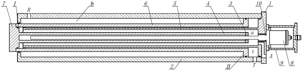
[0009] As shown in the drawings, the integrated single-rod symmetrical hydraulic cylinder with built-in displacement sensor of the present invention includes a magnetostrictive displacement sensor and a hydraulic cylinder, the hydraulic cylinder includes a cylinder body 2, and the magnetostrictive displacement sensor The main body of 8 is fixed on the cylinder bottom 1 by a sealing ring 10 .

[0010] The cylinder bottom 1 is fixed on the right end of the cylinder body 2, an air inlet T is opened on the side wall at the right end of the cylinder body 2, and a first liquid channel A is opened on the cylinder bottom 1 There is a second liquid passage B on the left side wall of the cylinder 2, a cylindrical fixed cavity 5 is arranged in...


PUM

PropertyMeasurementUnit
Resolutionaaaaaaaaaa

Abstract

The invention discloses a built-in displacement sensor integrated single piston rod symmetrical hydraulic cylinder which comprises a magnetic telescopic displacement sensor and a hydraulic cylinder body. The hydraulic cylinder body comprises a cylinder body. A main body of the sensor is fixed to the cylinder bottom through a sealing ring. An air inlet is formed in the side wall at the right end of the cylinder body. A first liquid channel is formed in the cylinder bottom. A second liquid channel is formed in the side wall of the left side of the cylinder body. A cylindrical fixing cavity is formed in the cylinder body. A hollow piston rod is installed between the outer wall of the fixing cavity and the inner wall of the cylinder body. The right end of the fixing cavity is fixed to the cylinder bottom. A boss is arranged at the right end of the piston rod. The outer wall of the boss can be in sliding fit with the inner wall of the cylinder body. A magnetic ring fixing cavity is installed in the fixing cavity. The left end of the magnetic ring fixing cavity is fixed to a piston end cover. A magnetic ring of the sensor is fixed to the right end of the magnetic ring fixing cavity. A magnetic telescopic rod of the sensor is inserted into the hollow cavity of the magnetic ring fixing cavity. Through the built-in displacement sensor integrated single piston rod symmetrical hydraulic cylinder, the stability in the working process of the hydraulic cylinder is maintained.

Description

technical field [0001] The invention relates to a fluid pressure actuator, in particular to a single-rod symmetrical hydraulic cylinder integrated with a built-in displacement sensor. Background technique [0002] A hydraulic cylinder is an actuator that converts hydraulic energy into mechanical energy for linear motion. A symmetrical hydraulic cylinder means that the two active surfaces of the hydraulic cylinder have the same area, while the single-rod hydraulic cylinder has unequal two active areas due to the piston rod in the rod cavity, which is an asymmetrical cylinder. The flow difference caused by the difference in area during the movement of the asymmetric cylinder will affect the control performance of the hydraulic cylinder. For pump-controlled hydraulic cylinders, directly change the speed and steering of the pump to control the speed and direction of movement of the hydraulic cylinder. The hydraulic system avoids throttling loss, reduces system heat generation, ...

Claims


Application Information

Patent Timeline
IPC IPC(8): F15B15/14F15B15/28
CPCF15B15/1423F15B15/2815F15B2215/30
Inventor 肖聚亮徐发达王国栋洪鹰
Owner TIANJIN UNIV
Learn More