Light directing film

A technology of light guide and thickness direction, applied in the direction of light guide, optics, optical components, etc.

Active Publication Date: 2016-12-14
UBRIGHT OPTRONICS CORP
View PDF11 Cites 2 Cited by
  • Summary
  • Abstract
  • Description
  • Claims
  • Application Information

AI Technical Summary

Problems solved by technology

It is not clear from this patent how the optical substrate is actually implemented

Method used


Image

  • Light directing film
  • Light directing film
  • Light directing film

Examples


Embodiment Construction

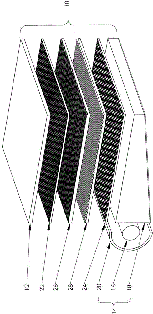
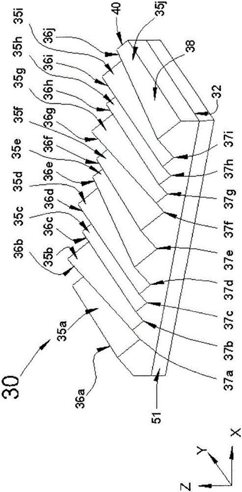
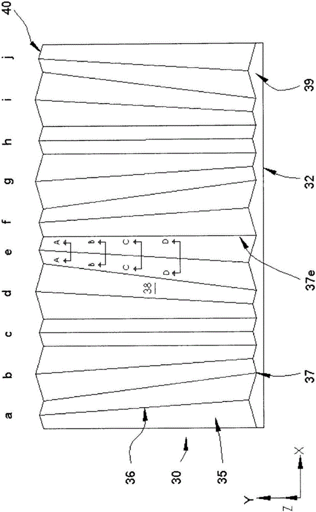
[0055] The present invention is directed to an optical substrate having a structured surface to enhance brightness and reduce moire effect. In one aspect of the present invention, the optical substrate is in the form of film, sheet, plate and other similar types, which can be movable or fixed, and has a three-dimensionally variable and structured light output surface that includes an Regular prism structure and an unstructured, smooth, flat light input surface. In the present invention, an optical substrate is connected to an LCD as an example. The LCD has an LC panel with a generally rectangular display area for introducing images.

[0056] figure 1 An example of a flat panel display will be described. A backlight LCD, one embodiment of the present invention, includes a liquid crystal (LC) display module 12, a planar light source in the form of a backlight module 14, and several optical films inserted between the LC module 12 and the backlight module 14. The LC module 12 c...


PUM


Abstract

The present invention discloses a light directing film comprising a first structured major surface, a second major surface opposite to the first structured major surface and a reference plane between the first structured major surface and the second major surface, wherein the reference plane is substantially perpendicular to the thickness direction of the light directing film, wherein the first structured major surface comprises a first prism element and a second prism element extending substantially in a first direction, wherein a first ridge of the first prism element has a first height relative to the reference plane and a second ridge of the second prism element has a second height relative to the reference plane, wherein the first height of the first ridge of the first prism element varies along the first direction. Preferably, the maximum of the first height is larger than the maximum of the second height.

Description

technical field [0001] The present invention relates to an optical substrate with a structured surface, in particular to an optical substrate capable of enhancing brightness, and more particularly to an optical substrate for a flat display with a flat light source. Background technique [0002] Flat panel display technology is widely used in TV monitors, computer monitors and handheld electronic products (such as: mobile phones, personal digital assistants (PDAs), etc.). Liquid crystal display (LCD) is one type of flat panel display, which incorporates a liquid crystal (LC) module with an array of pixels to display images. In a backlit LCD, the brightness enhancement film uses a prism structure to guide light along the line of sight axis (note: perpendicular to the display) to enhance the brightness of the display as seen by the user, thus enabling the system to use less energy to produce the desired on-axis lighting. [0003] To date, brightness enhancement films have bee...

Claims


Application Information

Patent Timeline
IPC IPC(8): G02B6/00
CPCG02B6/0036
Inventor 王康华杨景安潘汉聪
Owner UBRIGHT OPTRONICS CORP
Why Eureka
Try Eureka