
Method for calibrating relation between rotating shaft and camera based on constraint global optimization

A calibration method and global optimization technology, applied in image data processing, instrumentation, computing, etc., can solve problems such as inability to directly collect images of calibration boards

Active Publication Date: 2016-12-14
众趣(北京)科技有限公司
View PDF3 Cites 16 Cited by
  • Summary
  • Abstract
  • Description
  • Claims
  • Application Information

AI Technical Summary

Problems solved by technology

However, when the camera is fixed on the rotating shaft, the camera cannot directly collect images of the calibration plate fixed on the rotating shaft from different angles

Method used


Image

  • Method for calibrating relation between rotating shaft and camera based on constraint global optimization
  • Method for calibrating relation between rotating shaft and camera based on constraint global optimization
  • Method for calibrating relation between rotating shaft and camera based on constraint global optimization

Examples


Embodiment

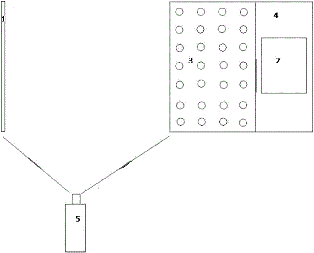
[0041] In this embodiment, a method for calibrating the relationship between the rotation axis and the camera based on constrained global optimization (hereinafter referred to as the calibration method) includes the following steps

[0042] 1) Use the turntable calibration plate 3 to calibrate the internal parameters of the large scene camera 5 and the camera 2 to be calibrated;

[0043] 2) When the rotating platform is at the starting position of the rotation, a picture of the calibration plate 1 is taken by the large scene camera and the camera respectively,

[0044] Starting from the starting position of the rotation, when the rotating shaft of the rotating platform rotates 360 degrees, the large scene camera rotates to 0°, 45°, 90°, 135°, 180°, 225°, 270°, and 315° in sequence. Take pictures of the calibration board 3 and get 8 series of pictures,

[0045] 3) The rotation matrix R of the calibration plate 1 to the large scene camera 5 coordinate system obtained from the p...


PUM


Abstract

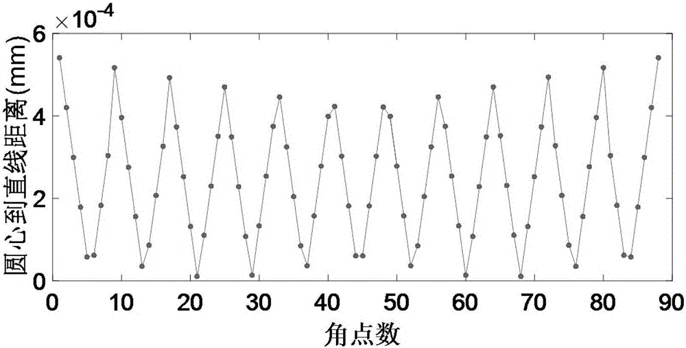
The invention discloses a method for calibrating the relation between a rotating shaft and a camera based on constraint global optimization, and the method comprises the following steps: 1), calibrating internal parameters of a big-view-field camera and a to-be-calibrated camera; 2), taking a series of images of a calibration plate in a 360-degree rotation process of a rotating platform through employing the big-view-field camera; 3), obtaining a rotation matrix and transition matrix of the calibration plate to the coordinate system of the big-view-field camera and a rotation matrix and transition matrix of the calibration plate to the coordinate system of the camera through the images, obtained at step 2), of the calibration plate; 4), obtaining a rotation matrix and transition matrix of a rotary table calibration plate rotating at one place to the coordinate system of the big-view-field camera through the image, taken by the big-view-field camera at step 2), of the rotary table calibration plate, extracting the three-dimensional coordinates of at least two corners of the rotary table calibration plate in the series of images, calculating the circle center coordinates of the track of each corner in a rotating process, carrying out the fitting of the straight line where all circle centers are located, and obtaining the inclined angle between the rotating shaft and the optical axis of the camera according to a rotating shaft direction vector and a camera optical axis direction axis.

Description

technical field [0001] The invention relates to the fields of machine vision, image processing and depth measurement, in particular to a calibration method for the relationship between a rotating shaft and a camera based on constrained global optimization. Background technique [0002] With the advent of the information age, the use of color digital cameras and depth cameras to simultaneously collect the color and depth information of the scene has been more and more widely used in various industries. But this type of camera can only collect data information in one direction. In order to obtain information of a larger range or 360-degree scene, it is necessary to move or rotate the camera to collect a series of two-dimensional or depth data. Especially indoors, the data of a larger field of view is often obtained by rotating the camera around the rotating platform at a known angle. By transforming the data obtained from different viewing angles into the same coordinate sys...

Claims


Application Information

Patent Timeline
IPC IPC(8): G06T7/00
CPCG06T2207/30244
Inventor 张宗华黄敏声刘强高翔
Owner 众趣(北京)科技有限公司
Learn More