
Ultrasonic wire drawing vibrator with asymmetric structure longitudinal-bend composite vibration

An asymmetric structure and compound vibration technology, applied in the direction of generator/motor, piezoelectric effect/electrostrictive or magnetostrictive motor, electrical components, etc., can solve complex excitation methods and degeneracy of longitudinal bending modal frequency and other problems to achieve the effect of simple structure, avoiding frequency degeneracy, and flexible design

Active Publication Date: 2019-03-15
HARBIN INST OF TECH
View PDF4 Cites 0 Cited by
  • Summary
  • Abstract
  • Description
  • Claims
  • Application Information

AI Technical Summary

Problems solved by technology

Although the longitudinal-bending composite vibrator of the ultrasonic vibrator can be realized functionally, the excitation method is complicated, and there is a problem of degeneracy of the longitudinal-bending mode frequency in the design process
However, the research on the ultrasonic vibrator that realizes longitudinal-bending compound vibration from the structure is still insufficient.

Method used


Image

  • Ultrasonic wire drawing vibrator with asymmetric structure longitudinal-bend composite vibration
  • Ultrasonic wire drawing vibrator with asymmetric structure longitudinal-bend composite vibration
  • Ultrasonic wire drawing vibrator with asymmetric structure longitudinal-bend composite vibration

Examples


Embodiment 1

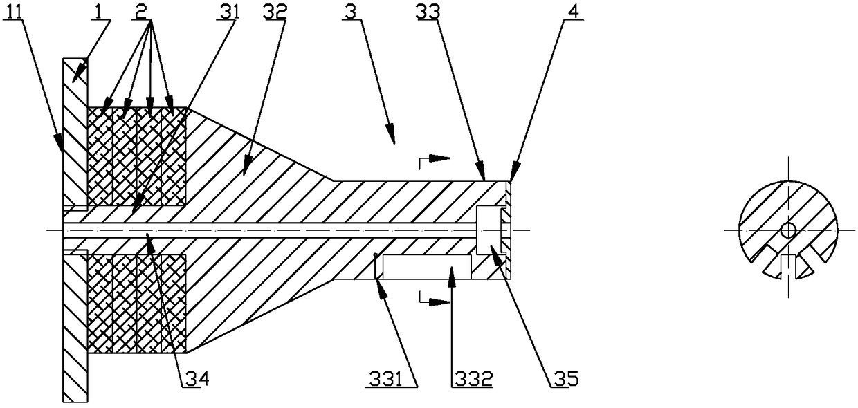
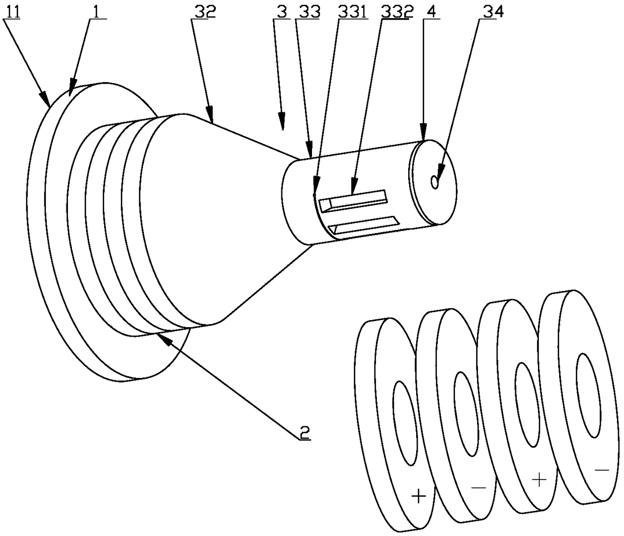
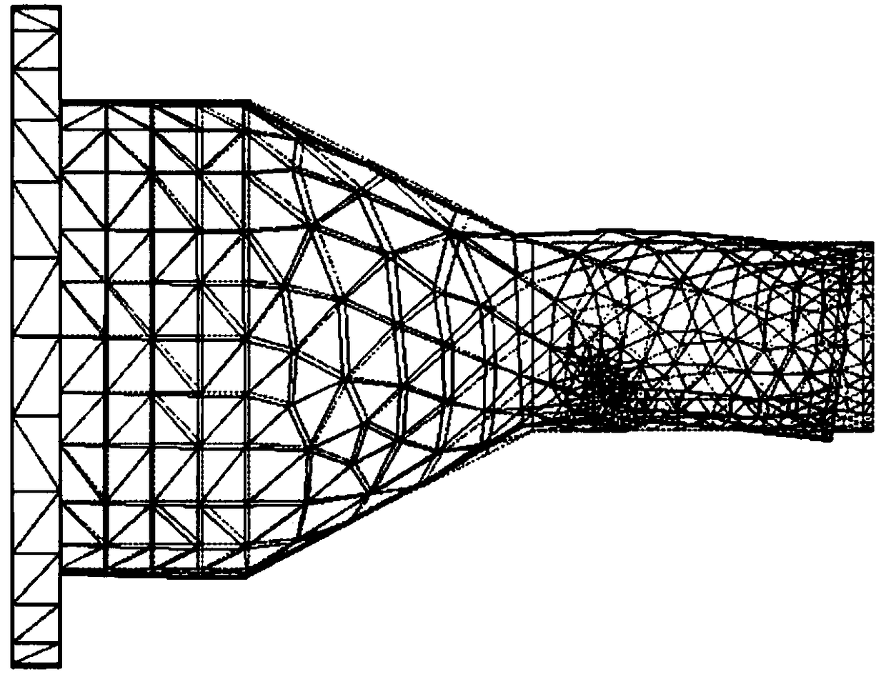
[0026] figure 1 It is a cross-sectional view of the ultrasonic wire drawing vibrator of the asymmetric structure longitudinal-bending composite vibration described in the present invention; figure 2 It is a schematic diagram of the geometry of the ultrasonic wire drawing vibrator of the asymmetric structure longitudinal-bend composite vibration described in the present invention and a schematic diagram of the polarization mode of the piezoelectric ceramic sheet; image 3 It is the longitudinal-bending composite vibration mode of the ultrasonic wire drawing vibrator of the asymmetric structure type longitudinal-bending composite vibration described in the present invention. combine Figure 1 to Figure 3 To describe the present invention in detail, the longitudinal bending composite ultrasonic wire drawing vibrator includes a rear end cover nut 1, four piezoelectric ceramic sheets 2, a composite horn 3, and a front end gland 4; the rear end surface of the rear end cover nut 1 ...

Embodiment 2

[0029]The difference between this example and Example 1 is that the slit 331 is set in the straight groove 332 and straddles the straight groove 332. The specific structure is as follows Figure 4 shown. All the other structures are the same as in Example 1.


PUM


Abstract

The invention brings forward an ultrasonic wave wire wire-drawing oscillator in an asymmetric structure for longitudinal flexural complex vibration, and belongs to the technical field of ultrasonic vibration wire wire-drawing oscillators, and solves problems that existing excitation methods of the longitudinal flexural complex vibration ultrasonic wave oscillators are complex and complex longitudinal flexural frequency degeneration exists in design processes. The ultrasonic wave wire wire-drawing oscillator includes a rear end cap nut, piezoelectric ceramic pieces, a composite amplitude-change pole and a front end gland. The rear end cap nut is connected with the composite amplitude-change pole; the composite amplitude-change pole includes a rear end small cross-section cylinder, a tapered rod, a cylindrical rod, a wire through hole and a wire-drawing die mounting hole; the piezoelectric ceramic pieces sleeve the rear end small cross-section cylinder; the rear end small cross-section cylinder, the tapered rod and the cylindrical rod are sequentially connected in succession; and a thin slot and a straight groove are arranged in the cylindrical rod. The ultrasonic wave wire wire-drawing oscillator in the asymmetric structure for the longitudinal flexural complex vibration proposed by the invention has the advantages of a simple excitation mode, flexible structure design, convenience for heat dissipation, high electromechanical coupling efficiency, etc.

Description

technical field [0001] The invention relates to an ultrasonic wire-drawing vibrator with an asymmetric structure type longitudinal-bending compound vibration, and belongs to the technical field of ultrasonic vibration wire-drawing vibrator. Background technique [0002] Piezoelectric ultrasonic vibration wire drawing is a processing technology in which ultrasonic vibration energy is superimposed in the conventional wire drawing process. The alternating electric signal generated by the ultrasonic driver is converted into ultrasonic vibration energy through the piezoelectric sheet, and then the ultrasonic vibration is amplified and matched by the horn. It can be transmitted to the wire drawing die to excite the vibration of the wire drawing die, and then the material to be processed is drawn through such a vibrating die to obtain the effect of ultrasonic vibration energy on the plastic forming of metal materials. [0003] The ultrasonic vibration drawing in the prior art is mo...

Claims


Application Information

Patent Timeline
Patent Type & Authority Patents(China)
IPC IPC(8): H02N2/00
CPCH02N2/003
Inventor 单小彪杨远才刘申谢涛
Owner HARBIN INST OF TECH
Learn More