Propshaft with constant velocity joint attachment

a constant velocity joint and propeller shaft technology, applied in the direction of yielding couplings, rotary machine parts, couplings, etc., can solve the problems of reducing the overall bending stiffness of the propeller shaft, and reducing the bending stiffness. , to achieve the effect of increasing the bending stiffness

Active Publication Date: 2008-03-25
AMERICAN AXLE & MFG
View PDF19 Cites 26 Cited by
  • Summary
  • Abstract
  • Description
  • Claims
  • Application Information

AI Technical Summary

Benefits of technology

[0001]The present invention relates to a propeller shaft assembly and, more particularly, to the attachment of a stub shaft and an inner race of a constant velocity joint which provides for increased bending stiffness.
[0005]The bending stiffness of a propeller shaft assembly is greatly influenced by the minimum diameter of the shaft and the length that the relatively small diameter extends from the loading points. Accordingly, the known forged stub shaft having a small diameter body may compromise the overall bending stiffness of the propeller shaft and, the longer the reduced body diameter extends, the lower the bending stiffness. It has been shown that the lower the bending stiffness, the more likely undesirable noise, vibration and harshness will be produced. Furthermore, existing propeller shaft assemblies may include a greater mass than necessary for transmitting rotary loads. Accordingly, it is desirable to reduce noise, vibration and harshness and reduce the weight of the propeller shaft assembly. Therefore, a need exists for an improved propeller shaft assembly having an increased bending stiffness and reduced mass.

Problems solved by technology

Accordingly, the known forged stub shaft having a small diameter body may compromise the overall bending stiffness of the propeller shaft and, the longer the reduced body diameter extends, the lower the bending stiffness.
It has been shown that the lower the bending stiffness, the more likely undesirable noise, vibration and harshness will be produced.
Furthermore, existing propeller shaft assemblies may include a greater mass than necessary for transmitting rotary loads.

Method used


Image

  • Propshaft with constant velocity joint attachment
  • Propshaft with constant velocity joint attachment
  • Propshaft with constant velocity joint attachment

Examples


Embodiment Construction

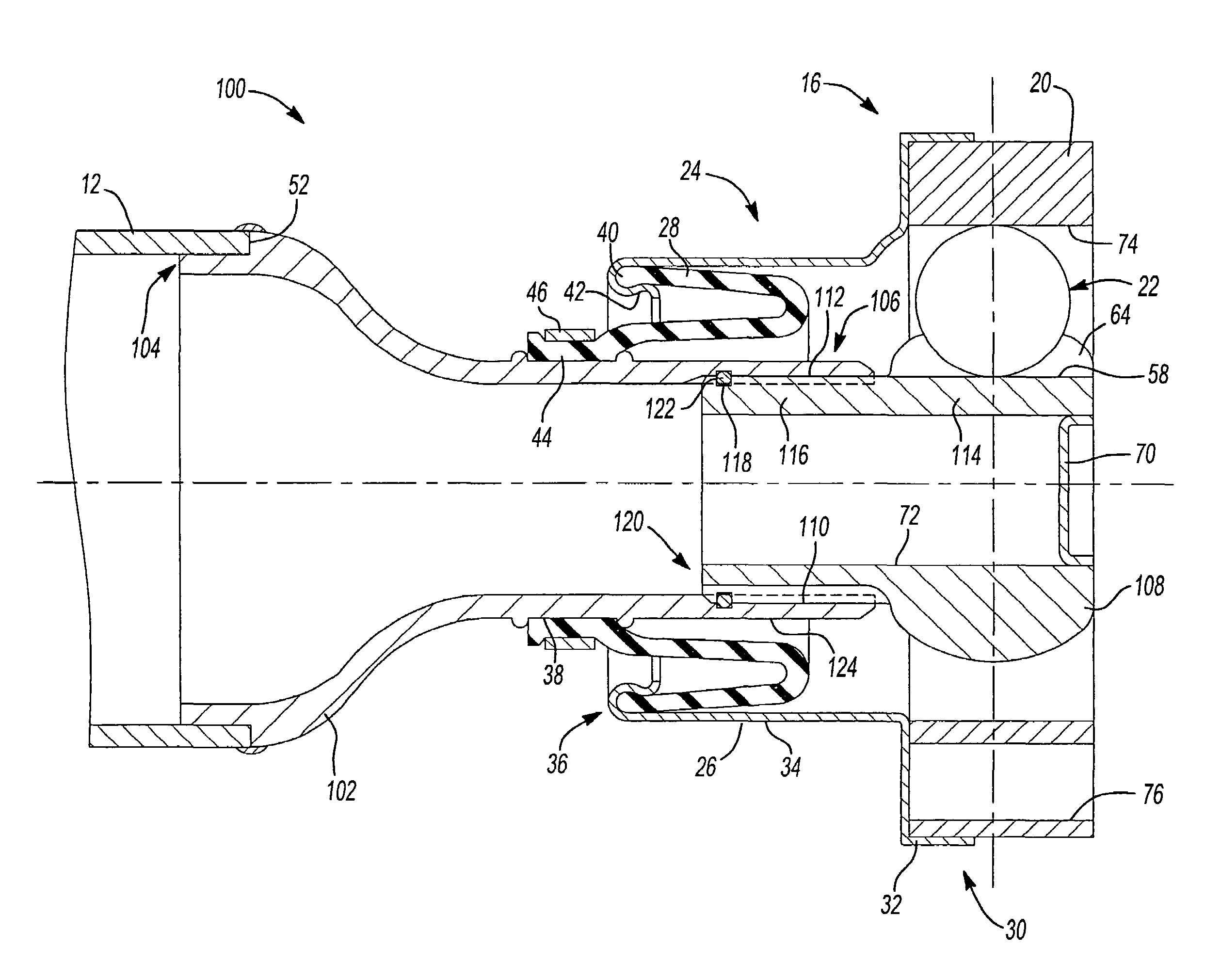
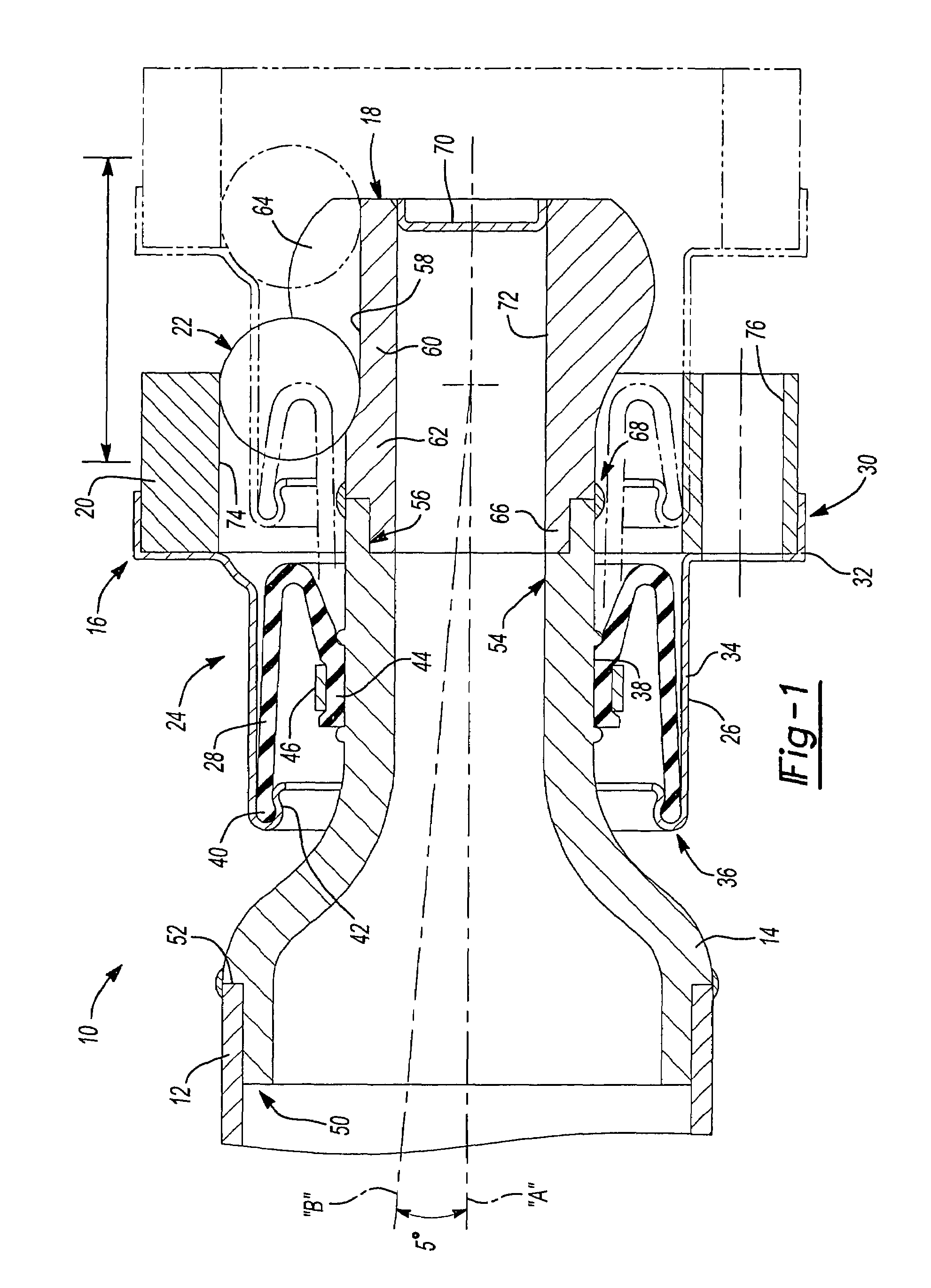
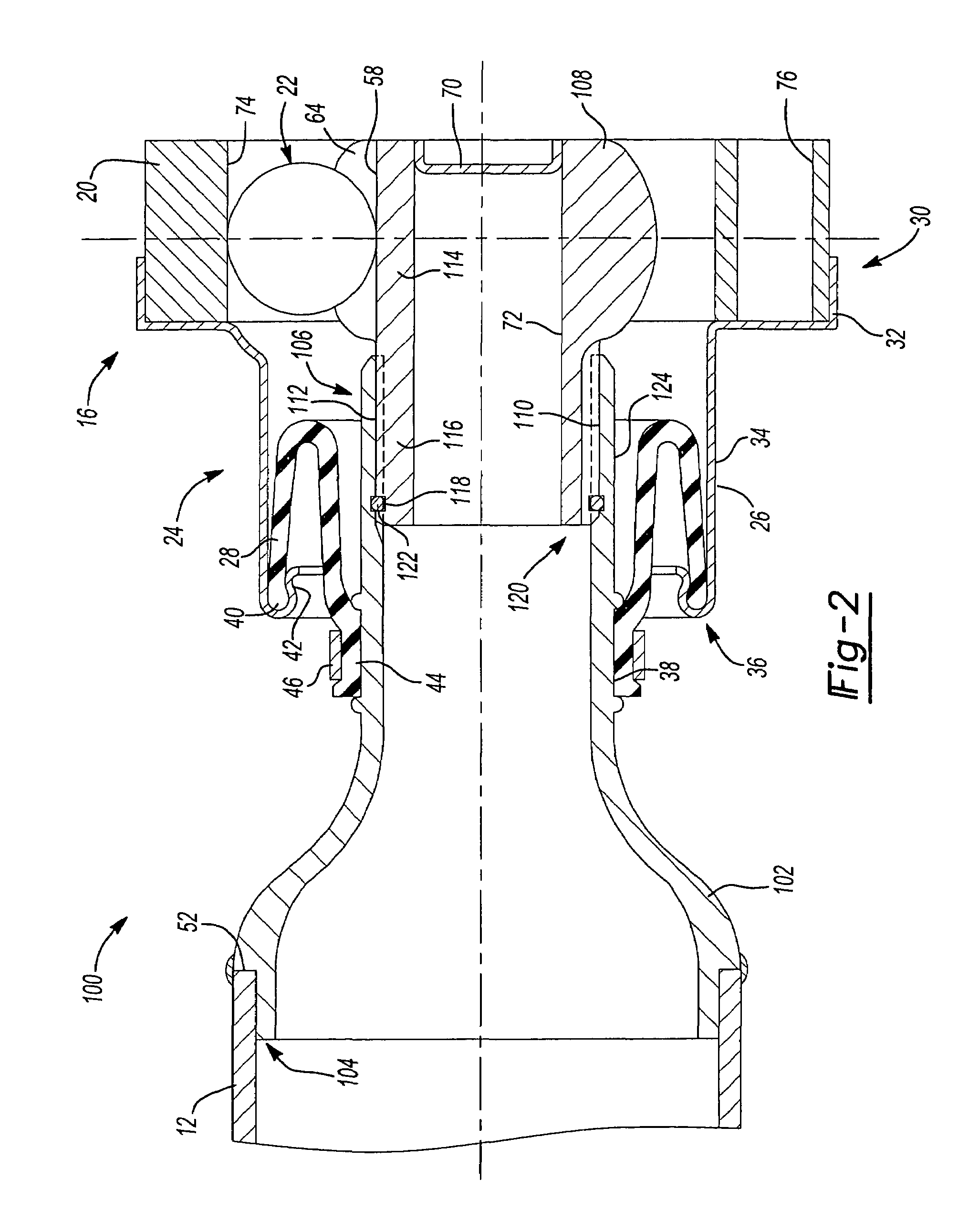
[0013]With reference to FIG. 1, a first embodiment propeller shaft assembly 10 includes a substantially cylindrical hollow propeller shaft 12, a stub shaft 14 and a constant velocity joint 16. Constant velocity joint 16 includes an inner race 18 and an outer race 20 drivingly interconnected with a plurality of balls 22. Constant velocity joint 16 also includes a cage (not shown) operable to maintain the axial alignment of balls 22. Propeller shaft 12, stub shaft 14 and inner race 18 are drivingly coupled to one another and rotate about a first axis “A”. Outer race 20 rotates about a second axis “B”. Constant velocity joint 16 is constructed to allow an angulation or misalignment between axis “A” and axis “B” up to about 5 degrees. A seal assembly 24 sealingly engages outer race 20 and stub shaft 14 to resist ingress of contamination to and retain grease within the region where the plurality of balls 22 engages the inner and outer race.

[0014]Seal assembly 24 includes a substantially ...


PUM


Abstract

A propeller shaft assembly includes a substantially cylindrical hollow propeller shaft, a stub shaft and a constant velocity joint having inner race and an outer race drivingly interconnected by a plurality of balls. The stub shaft has a first end fixed to the propeller shaft and a second end drivingly coupled to the inner race. The second end includes a portion positioned adjacent to the inner race that defines an outer diameter greater than an outer diameter defined by the interface between the inner race and the plurality of balls.

Description

BACKGROUND AND SUMMARY OF THE INVENTION[0001]The present invention relates to a propeller shaft assembly and, more particularly, to the attachment of a stub shaft and an inner race of a constant velocity joint which provides for increased bending stiffness.[0002]Typically, a vehicle propeller shaft drivingly interconnects a transmission assembly and an axle assembly such that the torque produced by the transmission is transferred through the propeller shaft to the axle thereby driving one or more of the vehicle wheels. Connecting assemblies drivingly connect the ends of the propeller shaft to any number of components including but not limited to a transmission, a power transfer unit, a torque transfer device or an independently mounted axle.[0003]Another type of propeller shaft includes multiple shafts or segments which are drivingly connected together and rotatably supported by a propeller shaft bearing assembly. The propeller shaft segments typically include a connecting assembly ...

Claims


Application Information

Patent Timeline
Patent Type & Authority Patents(United States)
IPC IPC(8): F16D3/223
CPCF16D1/068F16D3/22F16D3/845F16D2001/103Y10S464/906
Inventor WORMAN, JR., WILLIAM E.DOWNS, JAMES P.
Owner AMERICAN AXLE & MFG
Why Eureka
Try Eureka