Headlight control device
A technology for control devices and headlights, which can be used in projection devices, printing devices, signal devices, etc., and can solve problems such as difficult to recognize images
- Summary
- Abstract
- Description
- Claims
- Application Information
AI Technical Summary
Problems solved by technology
Method used
Image
Examples
no. 1 approach >
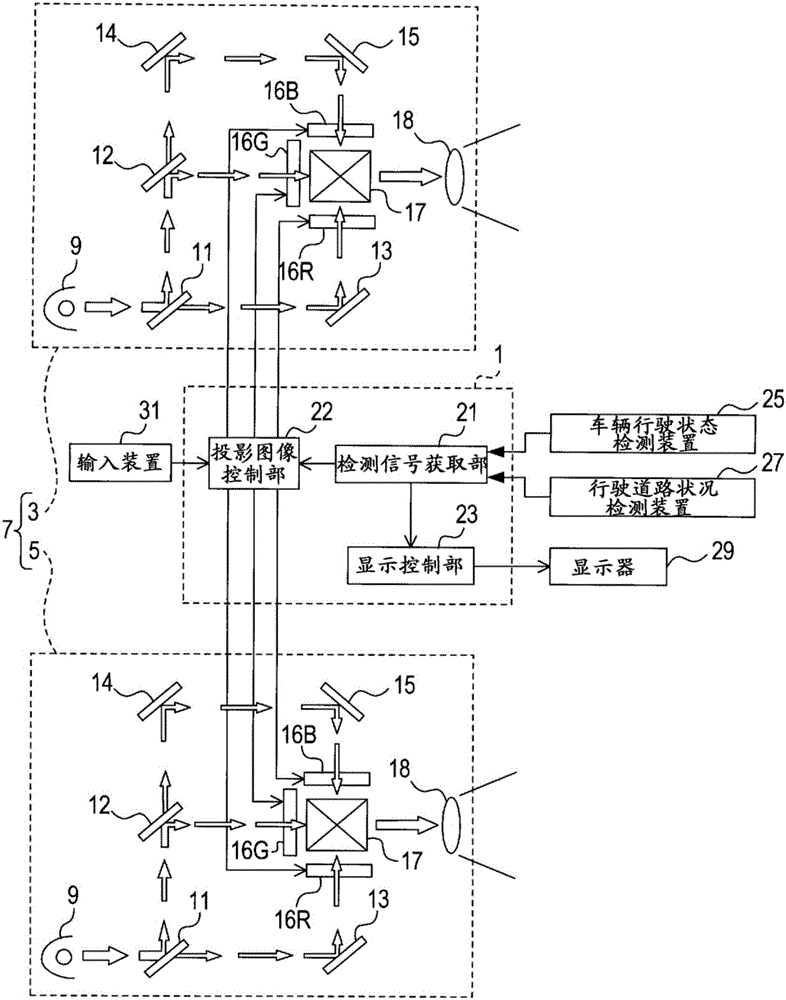
[0018] 1. Structure of the headlight control device 1 and the headlight device 7
[0019] based on figure 1 The structures of the headlight control device 1 and the headlight device 7 will be described. The headlamp control device 1 is an in-vehicle device that controls a headlamp device 7 including a pair of headlamp units 3 and 5 .
[0020] The headlamp unit 3 is disposed on the left side of the front end of the vehicle, and the headlight unit 5 is disposed on the right side of the front end of the vehicle. The headlamp units 3 , 5 each radiate light toward the front of the vehicle. The headlight units 3, 5 have the same structure. Here, the headlamp unit 3 will be described as an example.
[0021] The headlight unit 3 includes a light source 9 . As the light source 9 , various known lamps that can be used as a light source for vehicle headlights, such as a halogen lamp and a xenon lamp, can be used. The light source 9 is controlled to be turned on and off by the headl...
no. 2 approach >
[0054] 1. Structure of the headlight control device 1 and the headlight device 7
[0055] The structures of the headlight control device 1 and the headlight device 7 are basically the same as those of the above-mentioned first embodiment, with some differences. Hereinafter, the difference will be mainly explained.
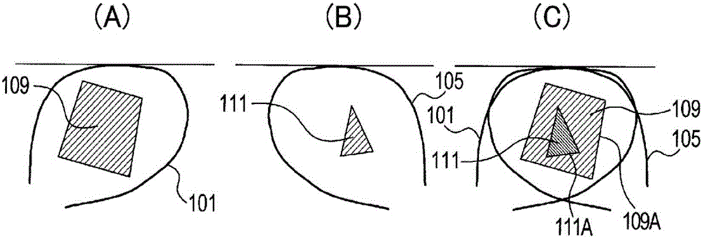
[0056] When the projected image control unit 22 projects a composite image of a specific shape on the road surface using the headlight units 3 and 5 , the liquid crystal panels 16R, 16G, and 16B of the headlight unit 3 and the liquid crystal panel of the headlight unit 5 16R, 16G, and 16B generate mutually different images.
[0057] That is, the projected image control unit 22 generates an image of a specific shape in a large size on the liquid crystal panels 16R, 16G, and 16B of the headlight unit 3 . As a result, as image 3 As shown in (A), in the synthesized light 101 irradiated from the headlight unit 3 , an image 109 of a specific shape is projected largel...
no. 3 approach >
[0065] 1. Structure of the headlight control device 1 and the headlight device 7
[0066] The structures of the headlight control device 1 and the headlight device 7 are basically the same as those of the above-mentioned first embodiment, but are partially different. Hereinafter, the difference will be mainly explained.
[0067] When the projected image control unit 22 projects a synthetic image of a specific shape on the road surface using the headlight units 3 and 5, no image is generated on the liquid crystal panels 16R, 16G, and 16B of the headlight unit 3, and the image is not generated on the headlight unit 3 . 5 liquid crystal panels 16R, 16G, 16B generate images.
[0068] That is, the projected image control unit 22 does not generate an image on the liquid crystal panels 16R, 16G, and 16B of the headlight unit 3, such as Figure 4 As shown in (A) of (A), the brightness of the synthesized light 101 irradiated from the headlight unit 3 is increased at any position.
...
PUM
 Abstract
Description
Claims
Application Information
 - R&D
- Intellectual Property
- Life Sciences
- Materials
- Tech Scout
- Unparalleled Data Quality
- Higher Quality Content
- 60% Fewer Hallucinations
Browse by: Latest US Patents, China's latest patents, Technical Efficacy Thesaurus, Application Domain, Technology Topic, Popular Technical Reports.
© 2025 PatSnap. All rights reserved.Legal|Privacy policy|Modern Slavery Act Transparency Statement|Sitemap|About US| Contact US: help@patsnap.com


