
Slip-controllable vehicle brake system

A technology for vehicle braking and wheel braking, applied in the direction of brakes, ABS control systems, etc., can solve the problems of sharpening and reconstruction, and achieve the effect of compact structure and low starting current.

Active Publication Date: 2016-12-14
ROBERT BOSCH GMBH
View PDF8 Cites 2 Cited by
  • Summary
  • Abstract
  • Description
  • Claims
  • Application Information

AI Technical Summary

Problems solved by technology

In order to be able to actuate the pressure generator even if there is a corresponding pressure, the drive of the pressure generator is designed accordingly, but requires a relatively large and heavy construction.
[0005] New system functions such as e.g. pedestrian protection exacerbate the above-mentioned problems

Method used


Image

  • Slip-controllable vehicle brake system
  • Slip-controllable vehicle brake system

Examples


Embodiment Construction

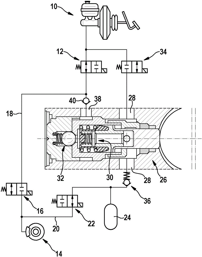
[0013] exist figure 1 The hydraulic connection diagram shown in shows the basically known brake circuit of a slip-adjustable vehicle brake system according to the connection symbols. The brake circuit also includes a master brake cylinder 10 which can be actuated by the driver by muscular force. The connection of the brake circuit to the main brake cylinder 10 is controllable via a switching valve 12 . In its basic position, the switchover valve 12 is open and can be switched to the off position by electromagnetic actuation. In the closed position of switchover valve 12 , it is not possible for the driver to vary the brake pressure at wheel brakes 14 connected to the brake circuit.

[0014] The brake circuit branches off downstream of the changeover valve 12 . A line branch leads via a pressure generating valve 16 in the form of a normally open 2 / 2 switching valve to the wheel brake 14 and thus forms its inflow 18 .

[0015] The return 20 branches off from the inflow 18 di...


PUM


Abstract

The invention relates to a slip-controllable vehicle brake system having a drivable pressure generator (26) for supplying at least one wheel brake (14) of a brake circuit with pressure medium. The pressure generator (26) is equipped with at least one pump inlet valve (30) and at least one pump outlet valve (32), to control the throughput of the pressure medium. Novel system functions, such as pedestrian protection, require that high pressure medium volumes be provided to the wheel brakes (14) increasingly faster. A corresponding design of the pressure generator (26) requires a drive having correspondingly increased power. For example, in the case of ABS braking, a high braking pressure generated by the driver works against the starting of the pressure generator (26) and increased starting currents occur on the drive. The modified design disadvantageously increases the weight and outside dimensions of the drive. In order to ease the starting of the drive and to limit the required starting current, according to the invention, means (40) are provided downstream of the pump outlet valve (32) which prevent an exerting of the pressure generator (26) on the pressure side (38) with the pressure of the main brake cylinder (10), at least at the start of pump conveying. More compact, lighter, and more cost-effective drives can be used for the pressure generator (26) as a result.

Description

technical field [0001] The invention relates to a slip-adjustable vehicle brake system designed according to the features of this type of claim 1 . Such a vehicle braking system is known, for example, from document DE 10 2010 042 534 A1. Background technique [0002] The known vehicle brake system comprises a hydraulic unit with a brake master cylinder connected thereto and likewise with wheel brakes connected thereto. In order to supply the vehicle brake system with brake pressure, the brake master cylinder is actuatable by the driver of the vehicle by muscular force. The brake pressure is supplied to the wheel brakes and is adapted by the control and regulating device of the hydraulic unit to the currently existing slip ratio at the vehicle wheels assigned to the wheel brakes. For this purpose, there are so-called pressure-generating valves and pressure-reducing valves on the hydraulic unit, which are assigned in pairs to each wheel brake. The pressure-generating valve ...

Claims


Application Information

Patent Timeline
Patent Type & Authority Applications(China)
IPC IPC(8): B60T8/40B60T8/48
CPCB60T8/405B60T8/4068B60T8/4872B60T8/341B60T2201/022B60T2270/10
Inventor W·舒勒G·奥伊泽坎
Owner ROBERT BOSCH GMBH
Learn More