Damper device

A vibration damping device and shock absorber technology, which can be used in transmission devices, fluid transmission devices, inertial effect shock absorbers, etc., can solve problems such as attenuation

Active Publication Date: 2016-12-14
AISIN AW CO LTD
View PDF7 Cites 4 Cited by
  • Summary
  • Abstract
  • Description
  • Claims
  • Application Information

AI Technical Summary

Problems solved by technology

In addition, in the vibration damping device as described above, the vibration that should be attenuated may not be dynamically damped due to the hysteresis of the elastic body for torque transmission, that is, the frictional force acting on the elastic body when the load decreases. Oscillators attenuate better

Method used


Image

  • Damper device
  • Damper device
  • Damper device

Examples


Embodiment Construction

[0020] Next, modes for implementing the present invention will be described with reference to the drawings.

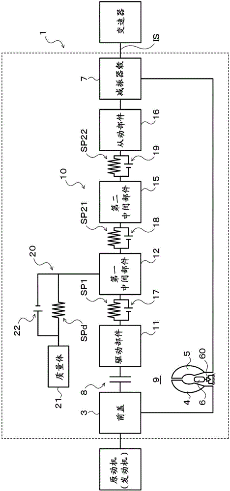
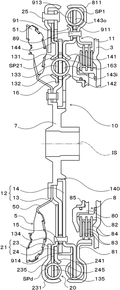
[0021] figure 1 is a schematic configuration diagram showing a starter device 1 including a vibration damping device 10 according to an embodiment of the present invention, figure 2 is a cross-sectional view showing the vibration damping device 10 . The starter device 1 shown in these drawings is mounted on a vehicle (for example, a front-wheel drive vehicle) provided with an engine (internal combustion engine) as a prime mover. The starter device 1 includes the following components in addition to the vibration damper 10, That is: the front cover 3 as an input part, which is connected with the crankshaft (output shaft) of the engine; the pump wheel (input side fluid transmission member) 4, which is fixed to the front cover 3; the turbine (output side fluid transmission member) 5, which It can rotate coaxially with the pump wheel 4; the damper hub 7, which is an outp...


PUM


Abstract

A damper device (10) includes: a dynamic damper coupled to a first intermediate member; and first and second inner springs (SP21, SP22) which operate in series with each other and which are straight coil springs interposed between a second intermediate member (15) and a driven member (16) so as to restrict an outward displacement of the springs (SP21, SP22) at the respective ends thereof in a radial direction of the damper device (10). A gap is formed between bodies (Bsp) of the first and second inner springs (SP21, SP22) and a spring contact portion (163) of the second intermediate member (15) or the driven member (16).

Description

technical field [0001] The present invention relates to a vibration damper including a plurality of rotating members, an elastic body that transmits torque between the plurality of rotating members, and a dynamic damper. Background technique [0002] In the past, as such a vibration damping device, the following devices are known, that is, equipped with: an output plate that rotates integrally with the turbine; a first coil spring that elastically connects the piston of the locking device and the output plate in the direction of rotation; It is provided to be relatively rotatable with respect to the output plate; and the second coil spring is arranged at a radially inner position than the first coil spring, and elastically connects the inertia member and the output plate in the direction of rotation (for example, refer to Patent Literature 1). The inertial member includes: an annular plate member; and an inertial member main body fixed to the outer peripheral portion of the...

Claims


Application Information

Patent Timeline
IPC IPC(8): F16F15/134F16F7/10F16F15/14F16H45/02
CPCF16H45/02F16F15/1217F16F15/12313F16F15/12373F16F15/1414F16H2045/0231F16H2045/0263F16F15/12366F16D3/12F16F15/12353
Inventor 伊藤一能大槻晃义平井悠一郎轮嶋雅树
Owner AISIN AW CO LTD
Why Eureka
Try Eureka