Vibration damping device

A vibration attenuation and engine technology, applied in the direction of transmission, fluid transmission, vibration suppression adjustment, etc., can solve problems such as large size, inability to attenuate vibration, and difficulty in ensuring sufficient restoring force

Inactive Publication Date: 2019-08-16
AISIN AW CO LTD +2
View PDF7 Cites 0 Cited by
  • Summary
  • Abstract
  • Description
  • Claims
  • Application Information

AI Technical Summary

Problems solved by technology

However, in the shock absorber described in Patent Document 1, the component of the centrifugal force is zero at the center of the swing range (see Figure 11 dotted line), so it is difficult to sufficiently ensure the above restoring force over the entire swing range
In addition, in the above-mentioned shock absorber, if the weight of the first link (crank member) and the inertial body are increased in order to increase the restoring force, the overall weight of the shock absorber will increase and the size will increase.
In addition, in the above-mentioned damper, if the weight of the first link cannot be increased due to weight and size constraints, the target vibration cannot be attenuated.

Method used


Image

  • Vibration damping device
  • Vibration damping device
  • Vibration damping device

Examples


Embodiment Construction

[0029] Next, modes for implementing the present invention will be described with reference to the drawings.

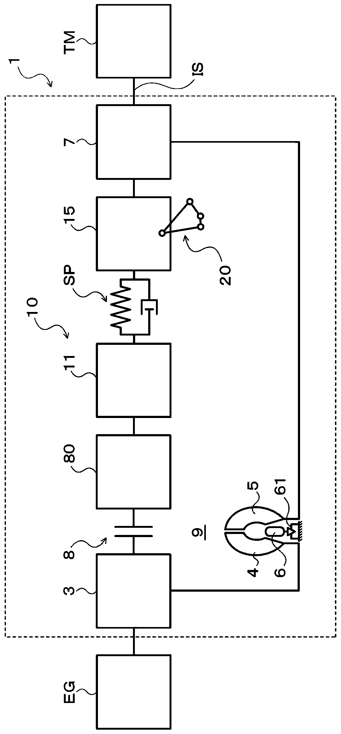
[0030] figure 1 It is a schematic structural diagram of the starting device 1 including the vibration damping device 20 of the present invention. The starting device 1 shown in this figure is mounted on, for example, a vehicle equipped with an engine (internal combustion engine) EG as a driving device (prime mover), and includes a The crankshaft connected to the front cover 3 as an input part, the pump wheel (input side fluid transmission member) 4 fixed to the front cover 3 and rotating integrally with the front cover 3, and the turbine wheel (output side) that can rotate coaxially with the pump wheel 4 Fluid transmission member) 5, fixed on the input shaft IS of the transmission (power transmission device) TM as automatic transmission (AT), continuously variable transmission (CVT), dual clutch transmission (DCT), hybrid transmission or speed reducer The damper hub...


PUM


Abstract

The invention provides a vibration attenuation device. The vibration attenuation device (20) is: connected to a driven part (15) via a first connection shaft (A1) and capable of rotating around the first connection along with the rotation of the driven part (15). The crank part (22) that the shaft (A1) swings; 22) The inertial mass body (24) swinging around the rotation center (RC) in an interlocking manner, with the rotation of the driven member (15) acting on the centrifugal force of the crank member (22) and from the first connecting shaft ( The component force in the direction perpendicular to the direction in which the center of A1) faces the center of gravity (G) always acts on the crank member (22) as a restoring force for returning the inertial mass body (24) to the center of the swing range. Maximum when the inertial mass (24) is in the middle of the swing range.

Description

technical field [0001] The present invention relates to a vibration damping device for damping vibration of a rotating member. Background technique [0002] Conventionally, there is known a shock absorber comprising: a link mechanism having a first connecting rod as a crank member connected to a crankshaft and a second connecting rod as a connecting rod connected to the first connecting rod; The connecting rods are connected to the crankshaft via the link mechanism to form an annular inertial body capable of relative rotation by a predetermined angle (for example, refer to Patent Document 1). In this shock absorber, the connecting point between the crankshaft and the first connecting rod is separated in the circumferential direction from the connecting point between the inertial body and the second connecting rod, and a mass body is formed on the first connecting rod. When the crankshaft rotates, the first link and the second link of the link mechanism are intended to be ke...

Claims


Application Information

Patent Timeline
Patent Type & Authority Patents(China)
IPC IPC(8): F16F15/14F16F15/31
CPCF16F15/1471F16F15/14F16F15/31F16D3/12F16F15/145F16F2228/001F16F2232/02F16H2045/0226F16H2045/0263
Inventor 泷川由浩长井大树轮嶋雅树坂本贵生刘孝宏中江贵志松崎健一郎
Owner AISIN AW CO LTD
Why Eureka
Try Eureka