Vibration damping device

A technology of vibration attenuation and shock absorber, which is applied in transmission devices, fluid transmission devices, vibration suppression adjustment, etc., can solve the problems of reduced vibration attenuation performance of shock absorbers and reduced vibration attenuation performance of shock absorber devices.

Inactive Publication Date: 2018-05-11
AISIN AW CO LTD
View PDF7 Cites 1 Cited by
  • Summary
  • Abstract
  • Description
  • Claims
  • Application Information

AI Technical Summary

Problems solved by technology

Therefore, when the weight (moment of inertia) of the connecting rod is increased to ensure strength and durability, the component force of the centrifugal force acting on the crank member is also used to return the connecting rod to a position in a balanced state. If the centrifugal force of the crank member, that is, the weight of the crank member is greatly increased, there is a concern that the vibration damping performance of the shock absorber will be reduced.
In addition, in the damper device described in Patent Document 2, there is an inflection point (position where the curvature changes) on the inner surface of the arcuate groove of the guide roller, so when the roller passes through the inflection point, the contact between the roller and the inner surface of the arcuate groove The position changes irregularly, and there is a possibility that the roller may slip or bounce
Moreover, if such sliding and bouncing of the rollers occurs, the vibration damping performance of the damper device will be reduced.

Method used


Image

  • Vibration damping device
  • Vibration damping device
  • Vibration damping device

Examples


Embodiment Construction

[0028] Next, an embodiment for implementing the invention of the present disclosure will be described with reference to the drawings.

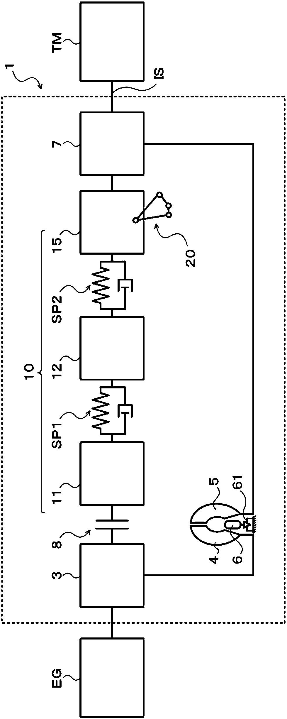
[0029] figure 1 It is a schematic configuration diagram of the starter device 1 including the vibration damping device 20 of the present disclosure. The starter device 1 shown in this figure is mounted on, for example, a vehicle equipped with an engine (internal combustion engine) EG as a driving device, and includes, in addition to a vibration damping device 20, a front cover 3 as an input member connected to the crankshaft of the engine EG, and fixed to the The pump impeller (input side fluid transmission member) 4 that rotates integrally with the front cover 3, the turbine wheel (output side fluid transmission member) 5 that can rotate coaxially with the pump impeller 4, and the automatic transmission (AT), without A shock absorber hub 7 as an output member, a lock-up clutch 8, and The shock absorber device 10 and the like.

[0030] In a...


PUM


Abstract

This vibration damping device includes: a supporting member which rotates integrally with rotating elements; restoring force generation members which are rotatably connected to the supporting member with first connecting shafts interposed therebetween; an inertia mass body which is rotatable about the center of rotation of the rotating elements; second connecting shafts which are each supported byone of the corresponding restoring force generation member and the inertia mass body, and connects the restoring force generation member and the inertia mass body in a relative rotatable manner; andguide portions which are each formed on the other side of the corresponding restoring force generation member and the inertia mass body, and guides the corresponding second connecting shaft. With therotation of the supporting member, each of the second connecting shafts rocks about the corresponding first connecting shaft while maintaining the center distance to the first connecting shaft constant, and rocks about a virtual shaft while maintaining the center distance to the virtual shaft constant, the virtual shaft being set so that the relative position with respect to the inertia mass bodyis invariant.

Description

technical field [0001] The disclosed invention relates to a vibration damping device that damps vibration of a rotating member. Background technique [0002] Conventionally, a shock absorber is known, which includes: a link mechanism including a first link as a crank member connected to a crankshaft and a second link as a connecting rod connected to the first link; The inertial body is connected to the second connecting rod and connected so as to be rotatable relative to the crankshaft at a predetermined angle via the link mechanism (for example, refer to Patent Document 1). In this shock absorber, the connecting point between the crankshaft and the first connecting rod is separated in the circumferential direction from the connecting point between the inertial body and the second connecting rod, and a mass body is formed on the first connecting rod. In addition, when the crankshaft rotates, the first link and the second link of the link mechanism tend to maintain a state o...

Claims


Application Information

Patent Timeline
Patent Type & Authority Applications(China)
IPC IPC(8): F16F15/14F16F15/134F16H45/02
CPCF16F15/134F16F15/1471F16H2045/0263F16F15/13469F16H45/02F16H2045/0231
Inventor 泷川由浩长井大树轮嶋雅树坂本贵生
Owner AISIN AW CO LTD
Why Eureka
Try Eureka