Dual-auxiliary-hole low-friction sliding self-ligating bracket
A self-locking bracket and auxiliary hole technology, used in brackets, medical science, dentistry, etc., can solve problems such as easy loss of torque, and achieve the effect of avoiding root absorption
- Summary
- Abstract
- Description
- Claims
- Application Information
AI Technical Summary
Problems solved by technology
Method used
Image
Examples
Embodiment 1
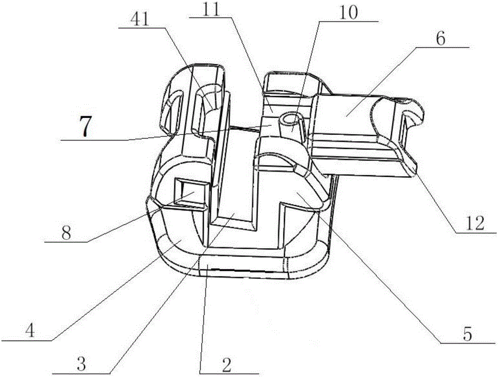
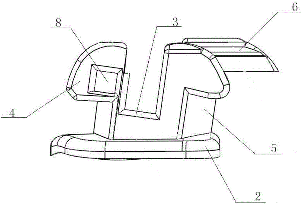
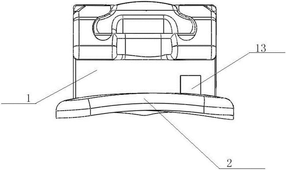
[0026] A low-friction sliding self-ligating bracket with double auxiliary holes, such as figure 1 and figure 2 and image 3 As shown, the self-ligating bracket is provided with a bracket main body 1 and a bonding base plate 2, and a bonding base plate 2 is provided below the bracket main body 1. The bracket main body 1 is provided with an arch wire groove 3 for installing an archwire, a positive The ligature wing 4, the auxiliary ligature wing 5 and the locking piece 6, the positive ligating wing 4 and the auxiliary ligating wing 5 are used to cooperate with the locking piece 6, and are used for the self-locking of the locking piece 6, and the arch wire groove 3 is set on the positive ligating wing Between 4 and the auxiliary ligation wing 5, the auxiliary ligation wing 5 is provided with a locking piece slot 7 which cooperates with the locking piece 6, and on the positive ligation wing 4 is provided a clip 41 which is used in cooperation with the front end of the locking pi...
Embodiment 2
[0029] A low-friction sliding self-ligating bracket with double auxiliary holes, such as figure 1 and figure 2 and image 3 As shown, the self-ligating bracket is provided with a bracket main body 1 and a bonding base plate 2, and a bonding base plate 2 is provided below the bracket main body 1. The bracket main body 1 is provided with an arch wire groove 3 for installing an archwire, a positive The ligature wing 4, the auxiliary ligature wing 5 and the locking piece 6, the positive ligating wing 4 and the auxiliary ligating wing 5 are used to cooperate with the locking piece 6, and are used for the self-locking of the locking piece 6, and the arch wire groove 3 is set on the positive ligating wing 4 and the auxiliary ligation wing 5, the auxiliary ligation wing 5 is provided with a locking piece 6 and a locking piece slot 7 used in conjunction with the locking piece 6, the locking piece 6 is actually a structure that can be flexibly disassembled, and the locking piece 6 is ...
Embodiment 3
[0033] Such as figure 1 and figure 2 and image 3 As shown, in order to better install and slide the locking piece in Embodiment 1 and Example 2, a guide rail 11 is provided on the edge of the locking piece slot 7, and sliding parts 12 that cooperate with the guide rail 11 are provided at both ends of the locking piece 6 . In order to make the lock piece 6 move more conveniently, guide rails 11 are designed on both edges of the lock piece slot 7, and here, the guide rail 11 is designed as two grooves, and the two grooves are respectively located at the two edges of the lock piece slot 7, Sliding parts 12 are designed on both edges of the locking piece 6, and the sliding parts 12 are set as two protrusions, that is, the locking piece 6 is designed into an I-shaped structure, which is convenient for sliding.
PUM
 Abstract
Description
Claims
Application Information
 - R&D
- Intellectual Property
- Life Sciences
- Materials
- Tech Scout
- Unparalleled Data Quality
- Higher Quality Content
- 60% Fewer Hallucinations
Browse by: Latest US Patents, China's latest patents, Technical Efficacy Thesaurus, Application Domain, Technology Topic, Popular Technical Reports.
© 2025 PatSnap. All rights reserved.Legal|Privacy policy|Modern Slavery Act Transparency Statement|Sitemap|About US| Contact US: help@patsnap.com


