
cranial catheter device

A catheter device and cranial cavity technology, applied in the direction of catheters, hollow probes, other medical devices, etc., can solve problems such as difficult, unusable, and complicated operations

Inactive Publication Date: 2020-06-16
李济范
View PDF11 Cites 0 Cited by
  • Summary
  • Abstract
  • Description
  • Claims
  • Application Information

AI Technical Summary

Problems solved by technology

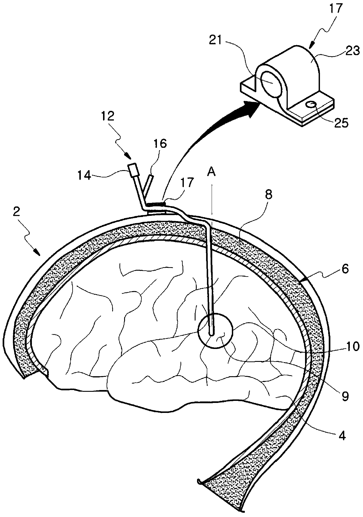
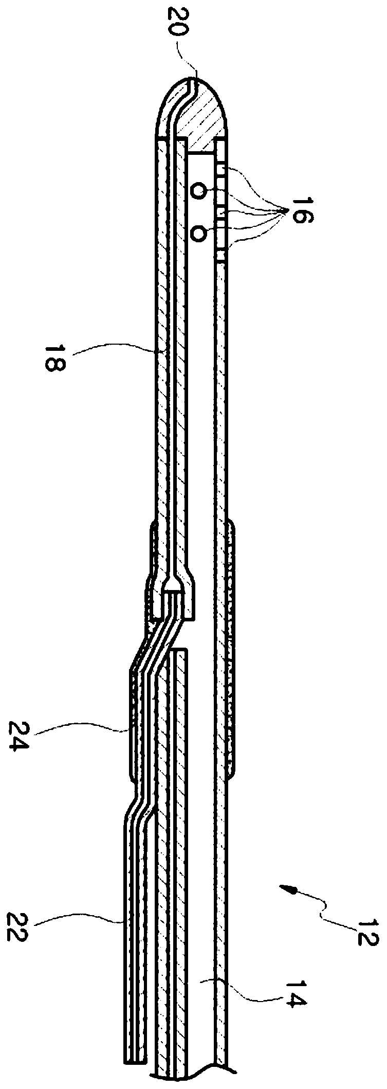
[0016] The catheter 12 is a structure in which the drug delivery tube 18 is connected to the drug injection tube 22 and connected by another connecting material 24. The connecting part and the drug injection tube 22 branched in a Y shape protrude outside the catheter 12, Therefore, not only can this instrument not be used, but also it is difficult to penetrate the tunnel at the rear end of the catheter 12 between the skull 6 and the skin 2, making the whole operation more complicated and difficult

Method used


Image

  • cranial catheter device
  • cranial catheter device
  • cranial catheter device

Examples


Embodiment Construction

[0038] The present invention will be described in detail below in conjunction with the accompanying drawings.

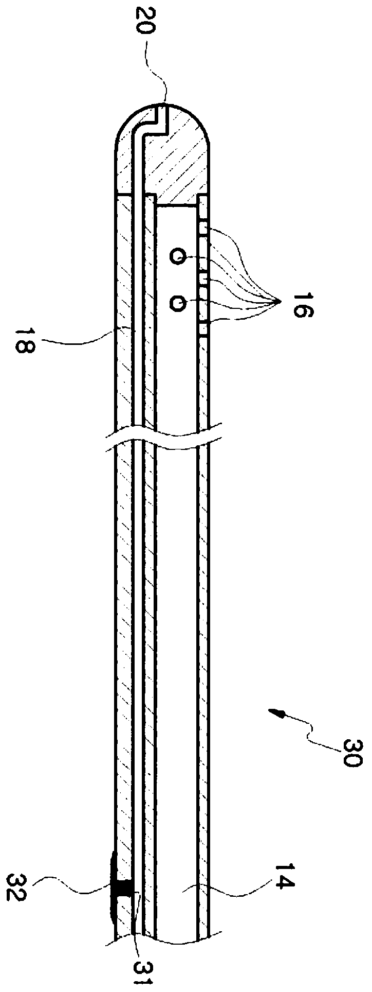
[0039] image 3 is a side sectional view showing a catheter for a cranial cavity according to an embodiment of the present invention; Figure 4 is a diagram showing the binding material on the cranial catheter device according to an embodiment of the present invention; Figure 5 is a diagram showing the combined state of the plastic tube, extension tube, and syringe; Figure 6a , 6b , 6c means Figure 4 A perspective view of the bonded state of the bundling material in .

[0040] In conjunction with the accompanying drawings, the cranial cavity catheter device according to the present invention maintains the advantages of the original catheter structure for transporting drugs and body fluids through different paths, and at the same time keeps the outer diameter of the catheter at a certain size, so that it is easier to use. A device that accurately positions the...


PUM


Abstract

The present invention relates to a catheter device for a cranial cavity. Advantages of a conventional catheter structure for transferring a drug and a bodily liquid through different pathways are maintained, and the outer diameter of a catheter is regularly formed, so a brain positioning device which is useful in accurately positioning a catheter end in a brain ventricle can be easily used. A catheter rear side can be easily tunneled in a round space between a skull and skin, so an operation can be conveniently and easily performed and operation safety is remarkably improved. According to the present invention, the outer diameter of a catheter does not have a protruding part, so a catheter end can be accurately and easily disposed in a brain ventricle of an affected area by using a brain poisoning device. Also, a catheter can be easily induced to be bent through a round space between the top of a skull and skin, and a catheter rear end part can be easily discharged to the outside of a cranial cavity through a punching unit.

Description

technical field [0001] The invention relates to a cranial cavity catheter device, specifically, while maintaining the advantages of the original catheter structure for transporting drugs and body fluids through different paths, the outer diameter of the catheter is kept at a certain size, so that it is easier to use. The end of the catheter is accurately located on the brain positioning instrument on the ventricle, and it makes it easier to penetrate the tunnel at the rear end of the catheter in the circuitous space between the skull and the skin, making the operation easier and greatly improving the safety of the cranial cavity Catheter device. Background technique [0002] It is well known that in the treatment of intraventricular hematoma, the underlying cause is treated and the hematoma is directly removed by neurosurgery craniotomy, but recently, direct insertion of Surgery to remove a hematoma or drain cerebrospinal fluid is more common, using a catheter or a brain-lo...

Claims


Application Information

Patent Timeline
Patent Type & Authority Patents(China)
IPC IPC(8): A61M25/14
CPCA61M25/0023A61M25/0028A61M2025/0037A61M2210/0693A61M25/0097A61M27/006A61M39/02
Inventor 李济范
Owner 李济范
Learn More