
Deburring device for plastic processing

A burr, plastic technology, used in grinding drives, metal processing equipment, grinding/polishing safety devices, etc., can solve the problem that plastics cannot be well adapted, and it is difficult to meet the needs of production. Product quality requirements, plastic products The side can not be cleaned and removed very well, so as to achieve the effect of strong adaptability and good adaptability

Inactive Publication Date: 2016-12-21
新昌县厚道机械有限公司
View PDF0 Cites 22 Cited by
  • Summary
  • Abstract
  • Description
  • Claims
  • Application Information

AI Technical Summary

Problems solved by technology

[0003] In the current plastic processing, burrs are often produced on the plastic due to mechanical processing. If these burrs are not dealt with in time, they will affect the subsequent processing quality. However, most of the current deburring devices can only remove the surface of the plastic. For The sides of plastic products cannot be cleaned and removed well, and at the same time, they cannot be well adapted to plastics of different thicknesses, which makes it difficult to meet the needs of production and product quality. Therefore, we propose a deburring device for plastic processing. to solve the above problems

Method used


Image

  • Deburring device for plastic processing
  • Deburring device for plastic processing
  • Deburring device for plastic processing

Examples


Embodiment Construction

[0017] The following will clearly and completely describe the technical solutions in the embodiments of the present invention with reference to the accompanying drawings in the embodiments of the present invention. Obviously, the described embodiments are only some, not all, embodiments of the present invention. Based on the embodiments of the present invention, all other embodiments obtained by persons of ordinary skill in the art without making creative efforts belong to the protection scope of the present invention.

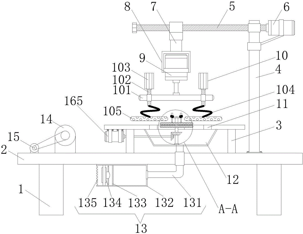
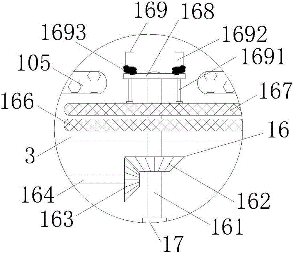
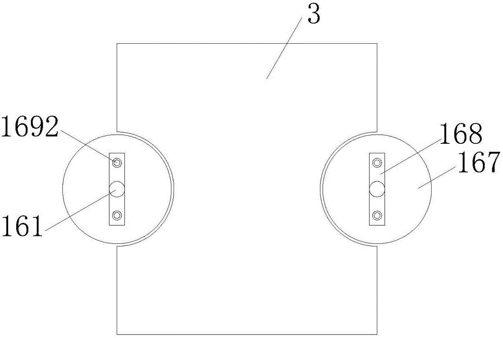
[0018] see figure 1 , a deburring device for plastic processing, comprising a leg 1, at least four legs 1 are provided, and the legs 1 are respectively fixedly installed on the four corners of the lower surface of the workbench 2, and the top of the leg 1 is fixedly installed with the workbench 2. The workbench 2 is made of rectangular steel. The upper surface of the workbench 2 is fixedly installed with the operation table 3. There is a gap between the operat...


PUM


Abstract

The invention discloses a deburring device for plastic processing. The deburring device comprises support legs. A workbench is fixedly mounted at the tops of the support legs. An operating platform is fixedly mounted on the upper surface of the workbench. A moving screw rod is movably mounted at the end, located on the side face of the operating platform, of the upper surface of the workbench through a support. An output shaft of a first servo motor is fixedly connected to one end of the moving screw rod, wherein the output shaft of the first servo motor is fixedly mounted at the top of the support. An electric extending-and-contracting rod is fixedly connected with the moving screw rod through a connection block. A clamping seat is fixedly mounted at the end, far away from the moving screw rod, of the electric extending-and-contracting rod. A first driving motor is fixedly mounted inside the clamping seat. According to the deburring device, edge clearing mechanisms are arranged, and therefore support shafts can be driven by a second servo motor to rotate; furthermore, the first edge clearing mechanism and the second edge clearing mechanism are made to rotate synchronously, so that the purpose of clearing burs at the side edges of a plastic product is achieved; and the production requirements and the requirements for product quality can be effectively met.

Description

technical field [0001] The invention relates to the technical field of plastic processing devices, in particular to a deburring device for plastic processing. Background technique [0002] Plastic refers to a material with plastic behavior. The so-called plasticity means that when an external force is applied, it deforms, and after the external force is removed, it can still maintain the state when the force is applied. The elastic modulus of plastic is between rubber and fiber, and it can deform to a certain extent under force. Soft plastics are closer to rubber and hard plastics are closer to fibers. [0003] In the current plastic processing, burrs are often produced on the plastic due to mechanical processing. If these burrs are not dealt with in time, they will affect the subsequent processing quality. However, most of the current deburring devices can only remove the surface of the plastic. For The sides of plastic products cannot be cleaned and removed well, and at ...

Claims


Application Information

Patent Timeline
Patent Type & Authority Applications(China)
IPC IPC(8): B24B9/20B24B27/00B24B41/00B24B41/02B24B55/06B24B55/12B24B47/12B29C37/02
CPCB24B9/20B24B27/0076B24B41/00B24B41/002B24B41/007B24B41/02B24B47/12B24B55/06B24B55/12B29C37/02
Inventor 袁熠明
Owner 新昌县厚道机械有限公司
Learn More