
Electric box carrying mechanical hand

A technology of manipulators and boxes, applied in the direction of manipulators, chucks, manufacturing tools, etc., to achieve the effect of simple structure, compact overall structure, convenient installation and maintenance

Inactive Publication Date: 2016-12-21
HARBIN UNIV OF SCI & TECH
View PDF5 Cites 31 Cited by
  • Summary
  • Abstract
  • Description
  • Claims
  • Application Information

AI Technical Summary

Problems solved by technology

[0003] The invention is an electric box handling manipulator, which mainly solves the problem of handling box parts of various sizes and different placement angles in the automatic production process

Method used


Image

  • Electric box carrying mechanical hand
  • Electric box carrying mechanical hand
  • Electric box carrying mechanical hand

Examples


Embodiment Construction

[0020] Structural principle of the present invention is described in detail below in conjunction with accompanying drawing:

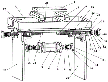
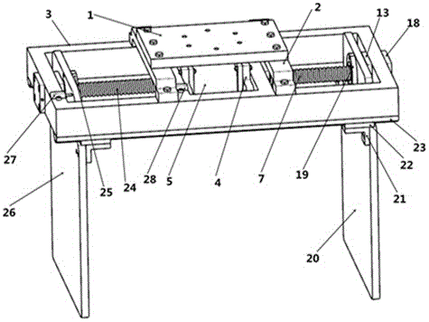
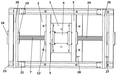
[0021] The electric box handling manipulator includes a fixed plate 1 connected to the end of the robot, a fixed support 2 installed under the fixed plate 1, a base 3 installed under the fixed support 2; a motor fixed seat installed inside the truss of the base 3 4. The double output shaft stepping motor 5 installed on the motor fixing seat 4, the double output shaft stepping motor 5 is connected with the ball screw 7 through the coupling 6, and the plane thrust bearing 8 is installed in the mounting hole of the base 3 , the plane thrust bearing 8 is installed on one end of the ball screw 7 through the bearing gasket 9 and the deep groove ball bearing 10, and the deep groove ball bearing 10 is installed on the base 3 together with the bearing end cover 12 through the bearing gasket 11; the bearing The end cover 13 is installed on the inner side of the t...


PUM


Abstract

The invention relates to a box carrying mechanical hand which is installed at the tail end of a carrying robot and using a stepping motor as a drive device. According to the structure of the box carrying mechanical hand, the two ends of the double-output-shaft stepping motor are connected with a left-handed ball screw pair and a right-handed ball screw pair through couplings. A right-handed ball screw nut is installed on a clamping plate I. A left-handed ball screw nut is installed on a clamping plate II. A deep groove ball bearing and a plane thrust bearing are installed at the two ends of each ball screw correspondingly. Pressure sensors are installed on outer side end covers and used for detecting axial pressure passing through the plane thrust bearings. Linear slide rails are installed on a base. Slide blocks are installed on the clamping plate I and the clamping plate II through triangular supports. The clamping plate I and the clamping plate II can move oppositely or reversely along the linear guide rails at the same time. A stroke switch I and a stroke switch II are installed on the two sides of the clamping plate I so that the limiting positions of two strokes can be detected. The box carrying mechanical hand is high in box carrying reliability, does not need other auxiliary devices and is simple in structure and convenient to install and maintain.

Description

technical field [0001] The invention belongs to the field of automatic production equipment, and in particular relates to an electric manipulator for carrying or sorting box parts in an automatic production line. Background technique [0002] In the automated production process, it is necessary to handle a large number of box-packed products or raw materials. Using the handling robot to realize the automatic handling of the box parts can greatly save manpower and production costs and improve production efficiency. The handling robot has the advantages of compact structure, mature technology, convenient control and quick action, and is widely used in various automated production processes. The manipulator for box handling is installed at the end of the robot to complete the grabbing and placement of box parts. At present, the design of the working method of the handling manipulator is relatively simple, and the adaptability to handling boxes of different sizes is poor. At t...

Claims


Application Information

Patent Timeline
Patent Type & Authority Applications(China)
IPC IPC(8): B25J15/02B25J15/08
CPCB25J15/0253B25J15/08
Inventor 张洪鑫宋现义王明珠
Owner HARBIN UNIV OF SCI & TECH
Learn More