Quick paper breaking re-winder

A rewinding machine and paper cutting technology, which is applied in metal processing and other directions, can solve the problems of toilet paper not being able to guarantee smoothness and low efficiency, and achieve the effect of conveniently fixing the stick shaft, high efficiency of work, and smooth paper roll

Inactive Publication Date: 2016-12-21
王艳丽
View PDF8 Cites 0 Cited by
  • Summary
  • Abstract
  • Description
  • Claims
  • Application Information

AI Technical Summary

Problems solved by technology

The traditional rewinder that cuts paper by knife cutting moves along the axial direction of the paper roll, and can only cut a section of paper at a time. This paper cutting method is not only inefficient, but also the toilet paper after knife cutting The cross-section cannot be guaranteed to be flat, especially for continuous operation rewinders

Method used


Image

  • Quick paper breaking re-winder
  • Quick paper breaking re-winder

Examples


Embodiment 1

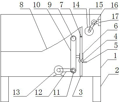
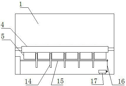
[0016] Such as figure 1 and figure 2 Shown, a kind of rapid paper break rewinding machine, it comprises frame 1, and the bottom of described frame 1 is equipped with support leg 2, and the right side of the top of described frame 1 is equipped with fixed plate 3, so The inner side of the fixed plate 3 is equipped with a stick shaft 4, the outside of the described stick shaft 4 is provided with a cardboard 5, the top of the described stick shaft 4 is connected with a connecting block 6, and the upper part of the fixed plate 3 is A distance sensor 7 is arranged on the outside, a slope surface 8 is connected to the top of the fixed plate 3, and a driven shaft 9 is arranged below the slope surface 8, and the driven shaft 9 is connected to the The driving shaft 11, the driving shaft 11 is connected with the transmission motor 13 through the main conveyor belt 12, the top right of the fixed plate 3 is provided with a cutting knife 14, and the cutting knife 14 is connected with the...

Embodiment 2

[0019] Such as figure 1 and figure 2 Shown, a kind of rapid paper break rewinding machine, it comprises frame 1, and the bottom of described frame 1 is equipped with support leg 2, and the right side of the top of described frame 1 is equipped with fixed plate 3, so The inner side of the fixed plate 3 is equipped with a stick shaft 4, the outside of the described stick shaft 4 is provided with a cardboard 5, the top of the described stick shaft 4 is connected with a connecting block 6, and the upper part of the fixed plate 3 is A distance sensor 7 is arranged on the outside, a slope surface 8 is connected to the top of the fixed plate 3, and a driven shaft 9 is arranged below the slope surface 8, and the driven shaft 9 is connected to the The driving shaft 11, the driving shaft 11 is connected with the transmission motor 13 through the main conveyor belt 12, the top right of the fixed plate 3 is provided with a cutting knife 14, and the cutting knife 14 is connected with the...


PUM


Abstract

The invention relates to a quick paper breaking re-winder. The re-winder comprises a frame, supporting legs are installed at the lower part of the frame, a fixed plate is installed on the right side of the upper part of the frame, a roll shaft is installed inside the fixed plate, a paper supporting plate is arranged outside the roll shaft, a distance sensor is arranged outside the upper part of the fixed plate, the top of the fixed plate is connected with a slope surface, a driven shaft is arranged below the slope surface, a cutter is arranged at the upper right part of the fixed plate, the cutter is connected with a driving belt via a rotating shaft, the driving belt is connected with a driving motor, the fixed plate can conveniently fix the roll shaft, the paper supporting plate can stably support re-wound toilet paper, and the toilet paper can thus be effectively prevented from slipping in the rising process of the paper supporting plate; when the paper roll rises to the position of the cutter, the paper roll is quickly cut by the cutter, and the cut paper roll slides down from the slope surface and enters next procedure; and the re-winder has the advantages of high paper breaking efficiency and high working efficiency, and the broken paper roll is flat.

Description

technical field [0001] The invention belongs to the technical field of paper product processing equipment, and in particular relates to a fast paper-breaking rewinder. Background technique [0002] In the process of producing paper rolls, the rewinder cuts the roll paper into small pieces of toilet paper every time a roll of roll paper is rewound, and then packs it. The traditional rewinder that cuts paper by knife cutting moves along the axial direction of the paper roll, and can only cut a section of paper at a time. This paper cutting method is not only inefficient, but also the toilet paper after knife cutting The cross-section cannot be guaranteed to be flat, especially for continuous operation rewinders. Contents of the invention [0003] The purpose of the present invention is to overcome the defects and deficiencies of the prior art, and provide a fast paper-breaking rewinder with high paper-breaking efficiency, smooth paper roll after paper breaking, and high wor...

Claims


Application Information

Patent Timeline
IPC IPC(8): B26D1/15B26D7/01B26D7/06B26D7/26B26D7/32
CPCB26D1/15B26D7/01B26D7/06B26D7/2621B26D7/32B26D2007/013
Inventor 王艳丽
Owner 王艳丽
Why Eureka
Try Eureka