

Triangular arm allowing angle of automobile wheel to be adjusted
A triangular arm and wheel technology, applied in the field of triangular arms, can solve the problems of lack of versatility, achieve the effects of reducing labor intensity and working time, reducing the design of abrasive tools, and eliminating deviation
- Summary
- Abstract
- Description
- Claims
- Application Information
AI Technical Summary
Problems solved by technology
Method used
Image

Examples
Embodiment 1
[0034] Embodiment 1 of the present invention, the difference between the technical solution of this embodiment and the existing triangular arm is:
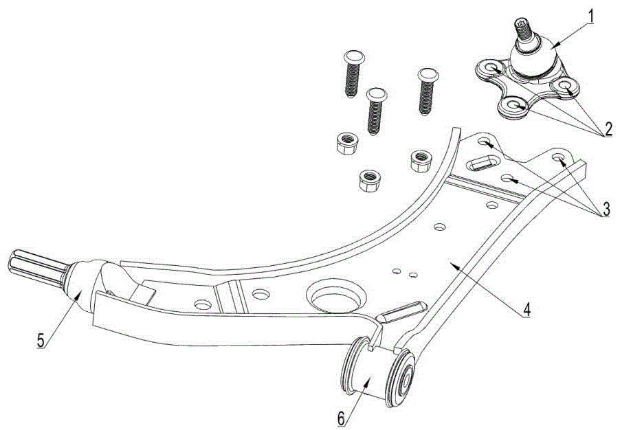
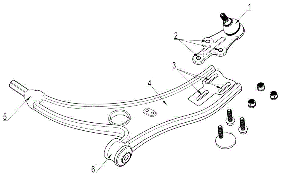
[0035] Such as figure 2 As shown, the three through holes A3 are all strip-shaped long holes or oval holes, and the through hole A3 far away from the first end of the triangular arm body and the corresponding through hole B2 on the ball head assembly The threaded bolt is the first eccentric bolt 9; the first eccentric bolt 9 includes the bolt head, the eccentric washer 22 and the screw rod, the bolt head, the eccentric washer and the screw rod are connected in sequence, and the eccentric washer 22 is integrated with the bolt head , in this embodiment the eccentric washer is a circular washer, and the center of the eccentric washer 22 deviates from the axis of the screw; Different parts of the first eccentric bolt contact to push the first eccentric bolt to slide in the through hole A limiting portion.
[0036] A structure of th...
Embodiment 2
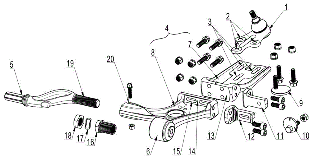
[0042] Embodiment two, such as image 3 , 4 , Shown in 5, the difference between the structure of this embodiment and embodiment one is:
[0043] The triangular arm body 4 is formed by connecting the first arm 7 and the second arm 8, one end of the first arm 7 is the first end of the triangular arm body connected with the ball joint assembly 1, and the other end of the first arm 7 is One end is movably connected to the second arm 8 through an eccentric adjustment assembly, and the eccentric adjustment assembly adjusts the installation position of the ball joint assembly by adjusting the relative position of the other end of the first arm on the second arm. The second end and the third end are arranged on the arm, the second end of the second arm is the second end of the triangular arm body connected with the rubber sleeve assembly, the third end of the second arm is the triangular arm connected with the fixed installation part The third end of the body.
[0044] The eccentr...
Embodiment 3
[0047] Embodiment three, the difference between the structure of this embodiment and the structure of embodiment one is:
[0048] The fixed installation part and the third end of the triangular arm body are connected by a detachable structure. The preferred solution is: the end face where the third end 20 of the triangular arm body 4 is connected to the fixed installation part is provided with an internal threaded hole in the axial direction, The outer wall of the third end of the triangular arm body is provided with a locking ear plate 20, and the middle part of the locking ear plate 20 is provided with a notch through the internal thread hole in the radial direction, and one end of the fixed installation part is provided with a connection Screw 19, the connecting screw 19 is threaded with the internal threaded hole through a connecting sleeve assembly capable of adjusting the relative connection position of the connecting screw and the internal threaded hole, and the connecti...
PUM
 Abstract
Description
Claims
Application Information