Power supply system

a power supply system and power supply technology, applied in the direction of capacitors, battery/fuel cell control arrangements, electric devices, etc., can solve the problems of dc power supply continuously overpowering or underpowering, unable to eliminate such deviations by feedback control, etc., to eliminate electric deviations

Active Publication Date: 2016-01-14
TOYOTA JIDOSHA KK
View PDF2 Cites 6 Cited by
  • Summary
  • Abstract
  • Description
  • Claims
  • Application Information

AI Technical Summary

Benefits of technology

[0007]An object of the present invention is to provide a power supply system which can prevent continuous overpower or underpower of a DC power supply on a voltage controlled side, by sufficiently compensating the electric distribution ratio among two or more power supplies to thereby eliminate an electric power deviation caused by sensor characteristics or the like.
[0009]In a power supply system according to the present invention, the controller may compensate the target output electric power of the first DC power supply by obtaining the difference between the actual output electric power of the second DC power supply and the target output electric power of the second DC power supply when an output state of the first DC power supply is stable.
[0014]With a power supply system according to the present invention, it becomes possible to prevent continuous overpower or underpower of a DC power supply on a voltage controlled side, by sufficiently compensating the electric power distribution ratio among two or more DC power supplies so as to eliminate an electric deviation caused by sensor characteristics on an electric power controlled side.

Problems solved by technology

Such a deviation may be caused by an offset error of a sensor which senses the electric current or voltage of the DC power supply.
However, because the offset error is undetectable in the control based on a sensed value obtained from a sensor, electric power of 100 may erroneously appear to be supplied to the load.
Such an electric power deviation caused by an offset of a sensed value obtained from a sensor (in other words, a difference between the electric power target value and the actual electric power value) cannot be detected as an electric power deviation in the control, and it is impossible to eliminate such a deviation by a feedback control such as by the power supply system in Patent Document 1.
As a result, the DC power supply may be continuously overpowered or underpowered (overcharged or overdischarged).

Method used


Image

  • Power supply system
  • Power supply system
  • Power supply system

Examples


Embodiment Construction

[0041]Embodiments according to the present invention are described in detail below with reference to the attached drawings. Because specific shapes, materials, values, direction, or the like in the description are presented as examples to facilitate understanding of the present invention, these may be changed depending on the usage, object, specifications, or any other conditions. Further, when two or more embodiments or variation examples are included below, any appropriate combinations of their features are originally expected.

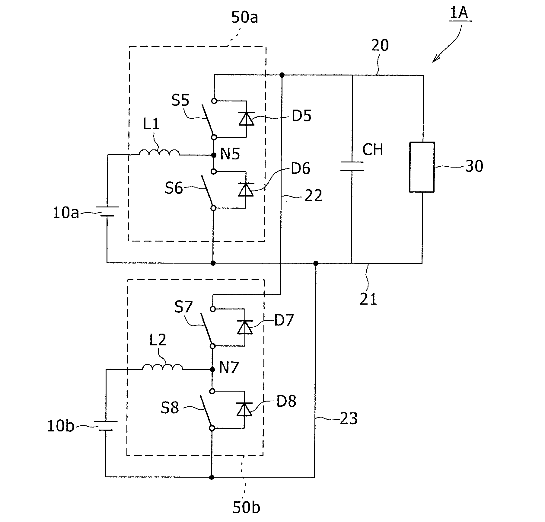
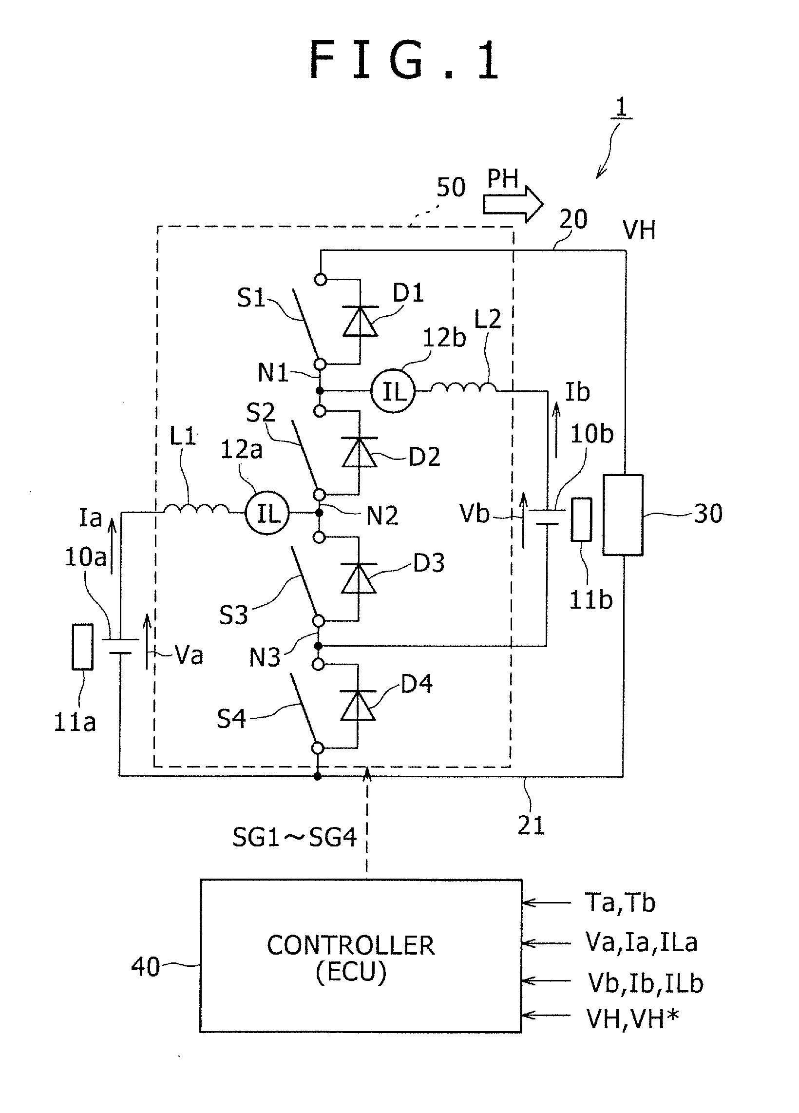
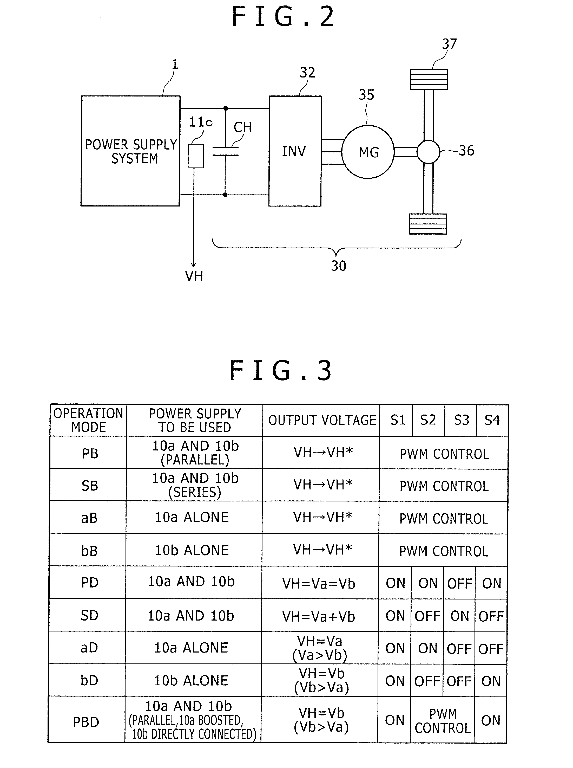
[0042]FIG. 1 shows a circuit diagram showing a configuration of a power supply system according to an embodiment of the present invention. A power supply system 1 includes a first DC power supply 10a, a second DC power supply 10b, a load 30, a controller 40, and an electric power converter 50.

[0043]In the present embodiment, each of the DC power supplies 10a, 10b is equipped with a secondary battery such as a lithium ion battery and / or a nickel-hydrogen batt...


PUM


Abstract

A power supply includes a load, an electric power line connected to the load, first and second DC power supplies which supply electric power to the load, an electric power converter connected between the electric power line and the first and the second DC power supplies, and a controller controlling the electric power converter. The first DC power supply serves for a voltage control, while the second DC power supply serves for an electric power control. The controller sets a difference between an electric power requested by the load and target output electric power of the first DC power supply as target output electric power of the second DC power supply, and compensates the target output electric power of the first DC power supply in accordance with a difference between the actual and the target output electric powers of the second DC power supply.

Description

PRIORITY INFORMATION[0001]This application claims priority to Japanese Patent Application No. 2014-142100, filed on Jul. 10, 2014, the entire disclosure of which is incorporated herein by reference.TECHNICAL FIELD[0002]The present invention relates to a power supply system which includes an electric power converter connected between two or more DC power supplies and a common power line.BACKGROUND ART[0003]JP 2011-97693 A (hereinafter referred to as “Patent Document 1”) discloses a conventional power supply system for a vehicle in which two DC power supplies are connected in parallel to an electric power line, via respective converters. In this power supply system, one of the DC power supplies is controlled by voltage and the other DC power supply is controlled by electric power by a feedback control such that the electric power requested from a motor (load) is supplied by the combination of these two DC power supplies. Further, in the power supply system, an electric power target va...

Claims


Application Information

Patent Timeline
Patent Type & Authority Applications(United States)
IPC IPC(8): H02J3/00B60L50/16
CPCH02J3/00B60L3/003B60L3/0046B60L3/04B60L7/14B60L15/007B60L15/20B60L15/2009B60L50/16B60L50/40B60L50/51B60L58/14B60L58/15B60L58/24B60L2210/14B60L2210/40B60L2240/421B60L2240/423B60L2240/525B60L2240/527B60L2240/545B60L2240/547B60L2240/549H02J1/14H02J7/00H02J2310/48Y02T10/64Y02T10/70Y02T10/7072Y02T10/72Y02T10/92
Inventor MITSUTANI, NORITAKE
Owner TOYOTA JIDOSHA KK
Why Eureka
Try Eureka