
a jacking machine

A technology for jacking and transplanting machines, applied in the field of conveyors, which can solve problems such as high air pressure requirements, easy tilting of guide posts, and easy failures, etc., to ensure level consistency, reduce design volume, and reduce electronic components Effect

Active Publication Date: 2018-09-21
JIANGSU HUAZHANG LOGISTICS TECH CO LTD
View PDF10 Cites 2 Cited by
  • Summary
  • Abstract
  • Description
  • Claims
  • Application Information

AI Technical Summary

Problems solved by technology

[0006] Aiming at the deficiencies of the above-mentioned prior art, the purpose of the present invention is to provide a jacking and transferring machine to solve the problem that the air pressure required by the jacking and transferring machine in the prior art is relatively high and the stroke of the cylinder is relatively large. , prone to failure; and the guide post between the base plate and the top plate is prone to problems such as tilting and jamming during movement

Method used


Image

  • a jacking machine
  • a jacking machine
  • a jacking machine

Examples


Embodiment Construction

[0022] In order to facilitate the understanding of those skilled in the art, the present invention will be further described below in conjunction with the embodiments and accompanying drawings, and the contents mentioned in the embodiments are not intended to limit the present invention.

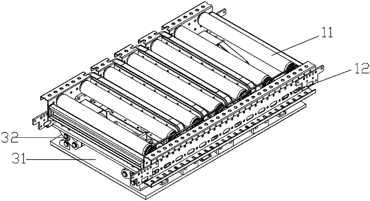
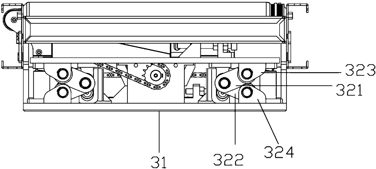
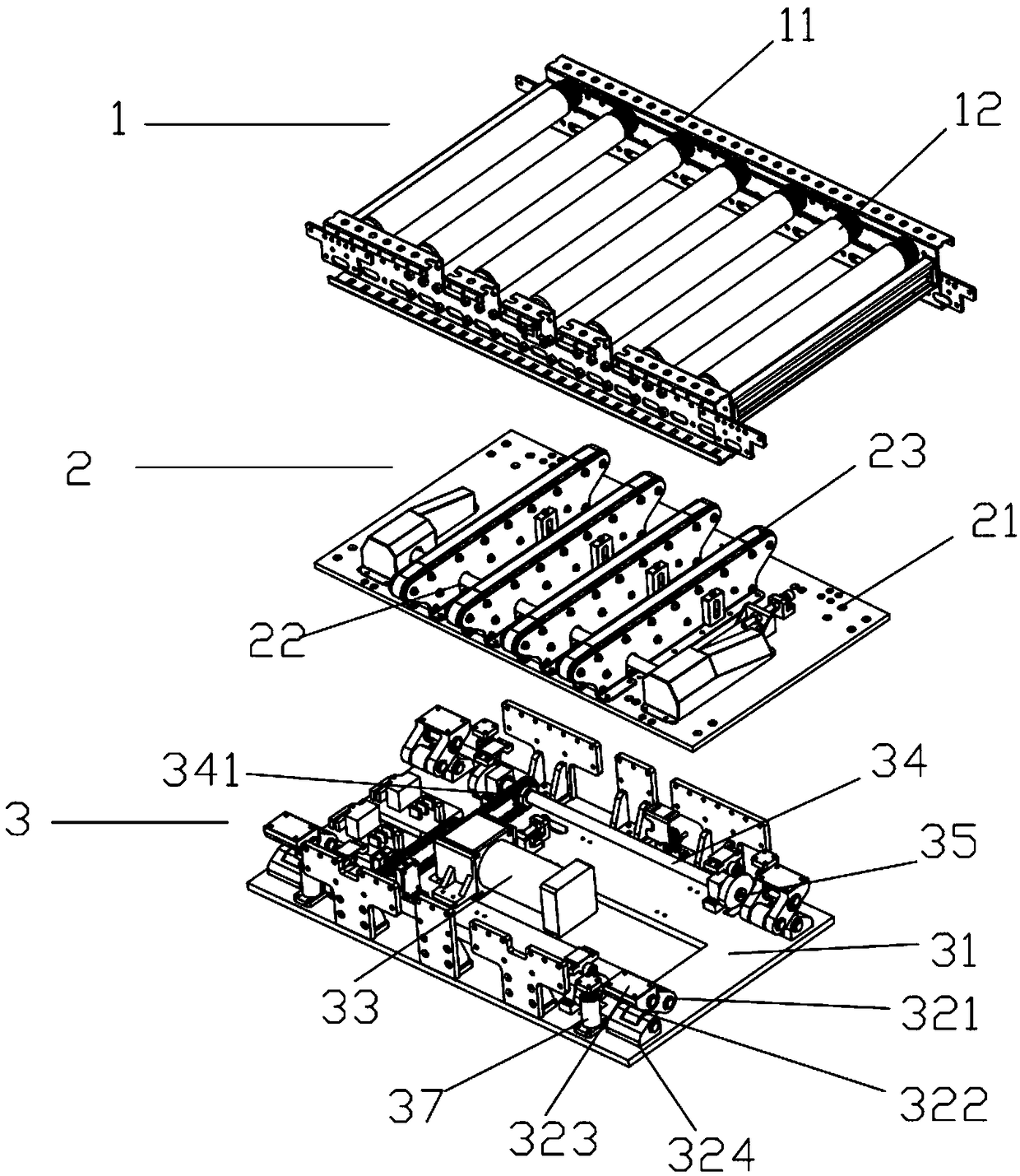
[0023] refer to Figure 1 to Figure 4 As shown, a jacking transfer machine of the present invention includes: a first conveying part 1, a second conveying part 2 and a jacking part 3; the first conveying part 1 is consistent with the conveying direction of the main line, and the second conveying part Part 2 intersects with the conveying direction of the main line, and the two are in a vertical direction during the transfer and conveying work;

[0024] The first conveying part 1 comprises: several conveying rollers 11 and side frames 12; the conveying rollers 11 are fixed on the side frames 12 at equal intervals, and the distance between two conveying rollers 11 axes is usually 120mm, accordi...


PUM


Abstract

The invention discloses a jacking transplanting machine. The jacking transplanting machine comprises a first conveying part, a second conveying part and a jacking part. The first conveying part is consistent with the direction of the main conveying line. The second conveying part intersects with the main conveying line. The jacking part comprises a base plate, four joint assemblies, a drive mechanism and a cam mechanism. The joint assemblies, the drive mechanism and the cam mechanism are all fixed to the base plate. The drive mechanism drives the cam mechanism to move so as to drive the second conveying part to rise and fall, and the relative height of cooperation of the first conveying part and the second conveying part is changed. The other ends of the joint assemblies are fixed to the second conveying part. The second conveying part rises and falls to drive the joint assemblies to be stretched out / drawn back. By means of the joint assemblies, supporting and limiting of a stop plate are achieved, the rolling and movable joint design is adopted, no stuck points exist, the horizontal consistency of the top plate in the rising and falling process is ensured, and the stuck phenomenon is avoided. The number of electronic components is small, the fault rate is low, and maintenance and installation are convenient.

Description

technical field [0001] The invention relates to the technical field of conveyors, and specifically refers to a jacking and transferring machine. Background technique [0002] In the product assembly line and warehousing and logistics handling, the conveying line is often used in the transportation of items. For example, a plurality of conveying lines are arranged vertically and horizontally in a delivery yard, and transfer machines are arranged at intersections of the conveying lines. Then, through the running transfer machine, the conveying direction of the article is changed, and the article is sent into or moved out of the main conveying line from the crossing position. The transfer machine enables items to enter and exit the main and auxiliary conveying lines conveniently, without collision, extrusion or even damage to the external structure due to the stacking of items during the transmission process. It is widely used in the field of industrial and logistics transmiss...

Claims


Application Information

Patent Timeline
Patent Type & Authority Patents(China)
IPC IPC(8): B65G47/53
CPCB65G47/53
Inventor 华聚良
Owner JIANGSU HUAZHANG LOGISTICS TECH CO LTD
Learn More