Fault indicator energy management method

A fault indicator and energy management technology, which is applied in the direction of fault location and fault detection according to conductor type, to solve energy management problems and improve accuracy

Active Publication Date: 2016-12-21
WUHAN ZHONGYUAN ELECTRONICS INFORMATION
View PDF7 Cites 3 Cited by
  • Summary
  • Abstract
  • Description
  • Claims
  • Application Information

AI Technical Summary

Problems solved by technology

The technical solution of the present invention uses the strength of the received signal to self-adaptively adjust the transmission power Pt of the fault indicator, and utilizes the power supply voltage of the fault indicator to self-adaptively select the cluster head to communicate with the communication terminal, thus solving the limitations and shortcomings of the existing solutions and realizing Efficient management of fault indicator energy and simultaneous sampling of fault indicators

Method used


Image

  • Fault indicator energy management method
  • Fault indicator energy management method
  • Fault indicator energy management method

Examples


Embodiment Construction

[0026] The technical solution of the present invention will be further described in detail below in conjunction with the accompanying drawings and specific embodiments.

[0027] On the A, B, and C phases at the same location of the overhead line, install the A-phase fault indicator, the B-phase fault indicator and the C-phase fault indicator respectively, and install a communication terminal on the power tower close to the fault indicator. 433MHz or 2.4GHz wireless communication modules are installed in the terminal, A-phase fault indicator, B-phase fault indicator and C-phase fault indicator, and each fault indicator communicates with the other two fault indicators and communication terminals through wireless communication. Module communication; each fault indicator has an indicator power supply voltage detection circuit to monitor the power supply voltage of the fault indicator in real time; the radio frequency transceiver chip of the wireless communication module has a recei...


PUM


Abstract

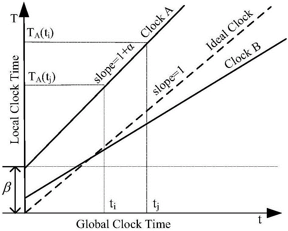
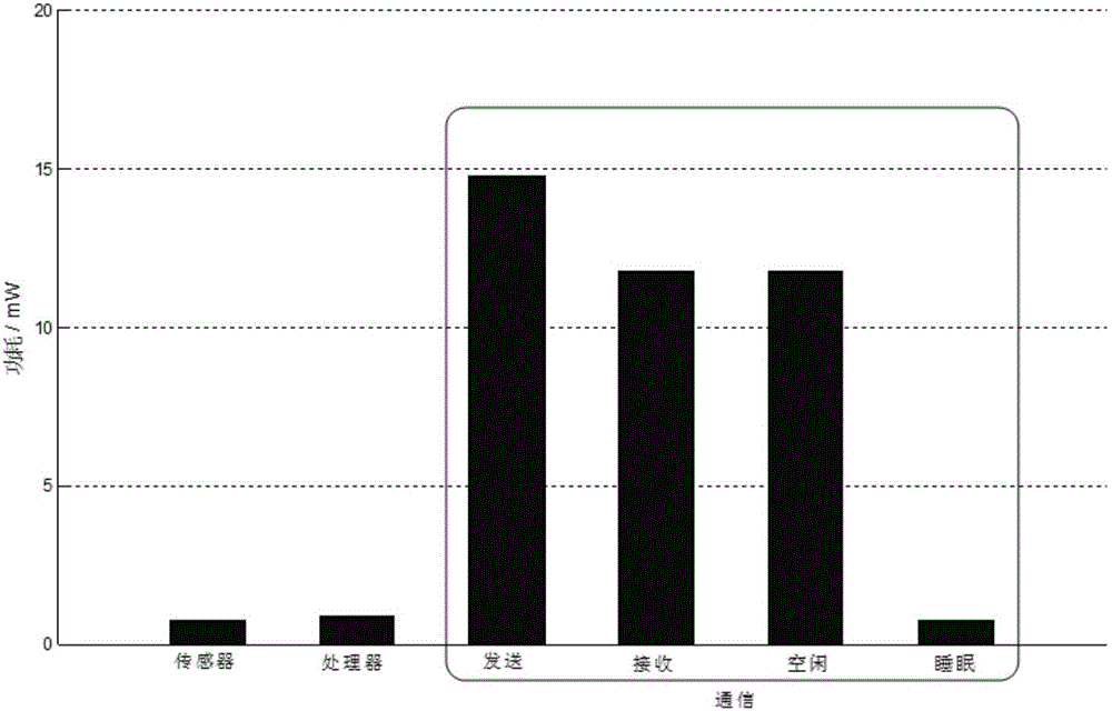
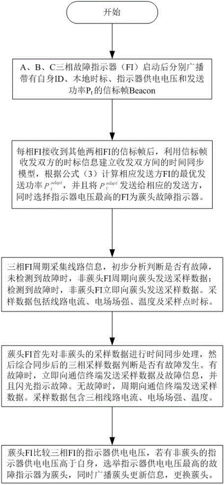
The invention discloses a fault indicator energy management method, which comprises the steps of: installing three fault indicators on three-phase lines separately; calculating a relative time drift and an initial time drift between the fault indicator to be synchronized and the master synchronization fault indicator; optimizing transmission power of the fault indicator serving as a wireless data transmitter; and selecting the cluster head fault indicator which receives sampling information of the non-cluster-head fault indicators, carrying out time synchronization on time marks of sampling points, and judging whether a fault occurs by utilizing the synchronized sampling information of the non-cluster-head fault indicators, sampling information of the cluster head fault indicator and a fault judgment algorithm. The fault indicator energy management method improves the accuracy rate of fault judgment of the fault indicators, greatly reduces the communication power consumption of the fault indicators, solves the problem of high failure false alarm and missed alarm rate of an existing fault indicator, and greatly enhances the feeder automation level.

Description

technical field [0001] The invention belongs to the technical field of fault location of electric power distribution network, and in particular relates to an energy management method of a fault indicator. Background technique [0002] In the distribution network system, there are many branches and complex operation conditions. When a short circuit or ground fault occurs, it is difficult to determine the fault section, which brings great difficulties to the maintenance work, especially in remote areas, and it takes time and effort to find it. With the advancement of distribution automation and rural power grid transformation in my country, fault indicators, as one of the technical means of distribution fault location, have been put into use in large quantities. Since the fault indicator is installed on the overhead line or in the cable trench, it is inconvenient to replace and maintain. Generally, energy harvesting CT and battery are used for power supply. The service life i...

Claims


Application Information

Patent Timeline
Patent Type & Authority Applications(China)
IPC IPC(8): G01R31/08
CPCG01R31/086
Inventor 王大兴张文魁张林桥张恒舫李欣
Owner WUHAN ZHONGYUAN ELECTRONICS INFORMATION
Why Eureka
Try Eureka