Annular-separation-based coin separation device
A coin separation and ring-shaped technology, applied in the detection field, can solve problems such as difficult to handle equipment, high cost of coin separation equipment, and limited use of coin separation equipment, and achieve the effect of improving separation efficiency
- Summary
- Abstract
- Description
- Claims
- Application Information
AI Technical Summary
Problems solved by technology
Method used
Image
Examples
Embodiment 1
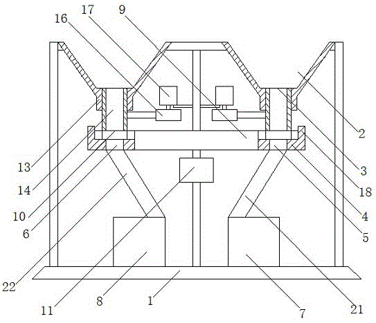
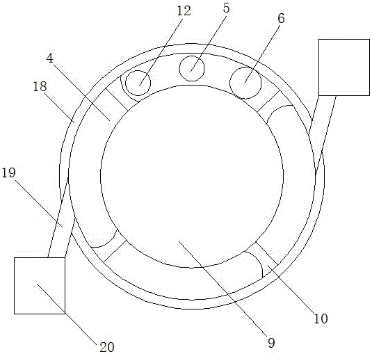
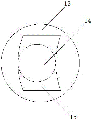
[0025] Such as figure 1 and figure 2A kind of coin separation device based on annular separation shown, it comprises frame 1, is provided with two discharge funnels 2 above frame 1, and its bottom end is provided with discharge port 3, and the bottom of discharge funnel 2 The lower end is provided with a coin separation disc 4 extending circularly in the horizontal direction, and the discharge port 3 in the discharge funnel 2 is opposite to the coin separation disc 4; a first separation tank is arranged in the coin separation disc 4 5 and the second separation tank body 6, which all extend between the upper end surface and the lower end surface of the coin separation disc 4, the first separation tank body 5 and the second separation tank body 6 all adopt a circular structure, and the first separation tank body The diameter of body 5 is less than the diameter of the second separation tank body 6, and it is respectively connected to the first collection tank 7 and the second c...
Embodiment 2
[0035] As an improvement of the present invention, four first separation tanks 5 are arranged on the coin separation tray 4 , and each first separation tank 5 is correspondingly provided with a color sensor 12 . By adopting the above-mentioned technical scheme, under the premise of not affecting the separation of one-dollar coins, a plurality of first separation tanks can be set to perform synchronous separation processing for multiple dime or five-cent coins, so that the overall separation efficiency of coins is improved.
[0036] The remaining features and advantages of this embodiment are the same as those of Embodiment 1.
Embodiment 3
[0038] As an improvement of the present invention, such as Figure 4 As shown, among the guide groove body 15, elastic springs 26 are respectively arranged between the side end surface of the feeding pipe 14 and the end of the guide groove body 15 in the horizontal direction, and the elastic spring 26 adopts an arc-shaped structure, and its It extends parallel to the extending direction of the guide groove body 15 . Adopting the above-mentioned technical scheme, it can be set by the elastic spring, so that during the movement process of the feeding pipe relative to the guide trough, it can improve its own operating efficiency under the elastic action of the elastic spring, and at the same time, it can effectively avoid falling. The feed pipe is stuck inside the guide tank, so as to further improve the efficiency and stability of the overall feed processing in which the feed pipe is connected to the feed hopper.
[0039] The remaining features and advantages of this embodiment...
PUM
 Abstract
Description
Claims
Application Information
 - R&D
- Intellectual Property
- Life Sciences
- Materials
- Tech Scout
- Unparalleled Data Quality
- Higher Quality Content
- 60% Fewer Hallucinations
Browse by: Latest US Patents, China's latest patents, Technical Efficacy Thesaurus, Application Domain, Technology Topic, Popular Technical Reports.
© 2025 PatSnap. All rights reserved.Legal|Privacy policy|Modern Slavery Act Transparency Statement|Sitemap|About US| Contact US: help@patsnap.com


