An emergency opening device

A brake device and emergency technology, which is applied in the direction of high-voltage air circuit breakers, electrical components, electric switches, etc., can solve problems such as damage to the opening electromagnet, failure of high-voltage circuit breakers, and power failure of the control power supply, so as to achieve large maintenance space and increase Large maintenance space, good locking effect

Active Publication Date: 2018-07-27
浙江智辉电力工程有限公司
View PDF4 Cites 0 Cited by
  • Summary
  • Abstract
  • Description
  • Claims
  • Application Information

AI Technical Summary

Problems solved by technology

The high-voltage circuit breaker is prone to accidents such as power failure of the control power supply and damage to the opening electromagnet during operation, resulting in the failure of the normal opening operation of the high-voltage circuit breaker. In the past, the emergency solution was to open the high-voltage switch cabinet door, and the operator would manually Reach into the cabinet and press the opening button of the high-voltage circuit breaker to force the manual emergency opening operation of the high-voltage circuit breaker. Because the operator is too close to the high voltage and there are no good precautions, it is easy to cause injury to the operator.
Usually the circuit breaker has an emergency opening and closing button for starting the mechanical opening and closing. However, since the circuit breaker is located in the switch cabinet, an emergency operating mechanism needs to be installed on the cabinet to operate the emergency opening and closing button. The existing Most of the emergency opening and closing devices of the switchgear have defects such as complex structure and poor reliability, which cannot meet the high requirements of use

Method used


Image

  • An emergency opening device
  • An emergency opening device

Examples


Embodiment Construction

[0012] The present invention will be further described in detail below in conjunction with the accompanying drawings and examples. The following examples are explanations of the present invention and the present invention is not limited to the following examples.

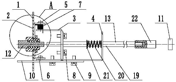
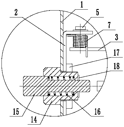
[0013] Such as figure 1 with figure 2 As shown, an emergency opening device includes a cabinet door 1, a C-shaped plate 2, a first bracket 3, a second bracket 4, an upper support pin 5, a lower support pin 6, a torsion spring 7, and fastening screws 8. Limit screw 9, limit support plate 10, high voltage circuit breaker opening button 11, button assembly 12, driven assembly 13. The C-shaped plate 2 is fixed on the inner side of the cabinet door 1, and the upper and lower ends of the first bracket 3 are hinged on the C-shaped plate 2 through the upper support pin 5 and the lower support pin 6 respectively, and the torsion spring 7 Set on the upper supporting pin shaft 5. The second bracket 4 is installed on the fi...


PUM


Abstract

The invention provides an emergency switching-off device, which belongs to the technical field of electric power equipment. The emergency switching-off device comprises a C-shaped plate, a button assembly and a driven assembly, wherein the upper end of a first bracket is hinged on the C-shaped plate by means of an upper supporting pin shaft, the lower end of a first bracket is hinged on the C-shaped plate by means of a lower supporting pin shaft, a torsional spring is arranged on the upper supporting pin shaft, a limiting screw is installed on a limiting support plate, a button supporting sleeve of the button assembly is installed on a cabinet door by means of a locking cushion plate, a button can be arranged in the button supporting sleeve in a left-right slidable manner, a button return spring is arranged between the button and the button supporting sleeve, a return baffle plate is attached to the button supporting sleeve under the action of the button return spring, the left end of an ejection rod return spring of the driven assembly is closely attached to an ejection rod supporting plate, the right end is closely attached to a second bracket, a trigger head is connected to the right end of an ejection rod in a threaded manner, and a high-voltage circuit breaker switching-off button is positioned on the right side of the trigger head. The emergency switching-off device realizes the switching-off of a high-voltage circuit breaker rapidly in an emergency state, and has the advantages of reasonable structure, good reliability, simple operation and sensitive response.

Description

technical field [0001] The invention relates to the technical field of electric equipment, in particular to an emergency opening device. Background technique [0002] Power equipment mainly includes two categories: power generation equipment and power supply equipment. Power generation equipment is mainly power plant boilers, steam turbines, gas turbines, water turbines, generators, transformers, etc. Power supply equipment is mainly transmission lines of various voltage levels, transformers, contactors and more. In the high and medium voltage switchgear, when the electrical opening and closing of the circuit breaker fails, it cannot be opened and closed reliably. In this case, it is necessary to open and close the switch urgently through a mechanical device. The high-voltage circuit breaker is prone to accidents such as power failure of the control power supply and damage to the opening electromagnet during operation, resulting in the failure of the normal opening operatio...

Claims


Application Information

Patent Timeline
Patent Type & Authority Patents(China)
IPC IPC(8): H01H33/42
CPCH01H33/42
Inventor 金永刚马雅兴曹海潮盛徐胤
Owner 浙江智辉电力工程有限公司
Why Eureka
Try Eureka