A limiter control circuit and method

A technology for controlling circuits and circuits, applied in circuit devices, electrical components, etc., can solve problems such as unstable operation of the driven resonant ring, and achieve the effect of solving unstable operation, decreasing inductance, and stabilizing voltage or current.

Active Publication Date: 2019-06-21
ZONECHARGE (SHENZHEN) WIRELESS POWER TECH CO LTD
View PDF4 Cites 0 Cited by
  • Summary
  • Abstract
  • Description
  • Claims
  • Application Information

AI Technical Summary

Problems solved by technology

[0005] In view of this, the present invention provides a limiter control circuit and method to solve the problem of unstable operation of the driven resonant ring

Method used


Image

  • A limiter control circuit and method
  • A limiter control circuit and method
  • A limiter control circuit and method

Examples


Embodiment Construction

[0030] The following will clearly and completely describe the technical solutions in the embodiments of the present invention with reference to the accompanying drawings in the embodiments of the present invention. Obviously, the described embodiments are only some, not all, embodiments of the present invention. Based on the embodiments of the present invention, all other embodiments obtained by persons of ordinary skill in the art without making creative efforts belong to the protection scope of the present invention.

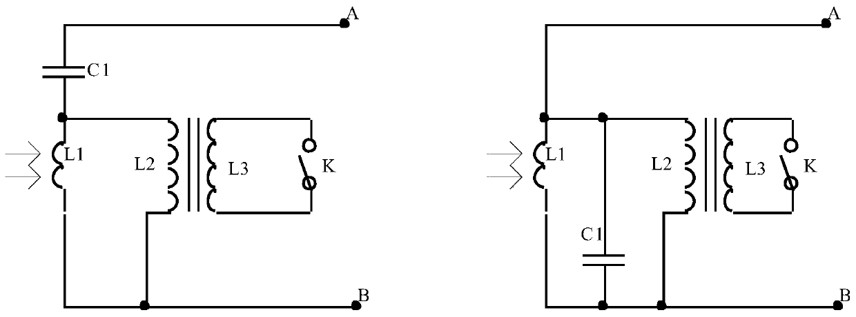
[0031] The present invention provides a limiter control circuit, the circuit comprising:

[0032] Resonant coils, resonant capacitors, switches and transformers;

[0033] The resonant coil is connected in parallel or in series with the resonant capacitor; the primary coil of the transformer is connected in parallel with the resonant coil; the secondary coil of the transformer is connected in series with the switch.

[0034] refer to figure 1 , figure 1 In t...


PUM


Abstract

The invention provides an amplitude limiting control circuit and a method thereof. The circuit comprises a resonance coil, a resonant capacitor, a switch and a transformer. The resonance coil and the resonant capacitor are connected in parallel or are connected in series. A primary coil of the transformer is connected in parallel with the resonance coil. A secondary coil of the transformer is connected in parallel with the switch. When a stable voltage needs to be provided, the switch is controlled to be conducted. Meanwhile, the secondary coil of the transformer is in a short circuit state, an inductance of the primary coil of the transformer is decreased and a total inductance amount of the whole circuit is reduced so that a resonant state is changed. The stable voltage or current can be provided and a problem that a driven resonance ring works unstably is solved.

Description

technical field [0001] The present invention relates to the field of wireless power supply, and more specifically, relates to a limiter control circuit and method. Background technique [0002] The driven resonant ring has the dual characteristics of receiving energy and transmitting energy. In the wireless power supply terminal, the driven resonant ring is often used as a receiving resonant ring to supply power to terminal appliances. [0003] Since the driven resonant ring works in a resonant state, the voltage and current amplitude in the resonant ring is large and unstable. If the power is directly supplied to the terminal electrical appliances, huge current and voltage fluctuations will be generated, which will have a serious impact on the terminal electrical appliances. , and even burn electrical appliances. [0004] Therefore, there is an urgent need for a circuit that controls the voltage or current amplitude of the driven resonant ring to ensure stable operation of...

Claims


Application Information

Patent Timeline
Patent Type & Authority Patents(China)
IPC IPC(8): H02J50/12
Inventor 徐宝华朱斯忠何智张福元
Owner ZONECHARGE (SHENZHEN) WIRELESS POWER TECH CO LTD
Why Eureka
Try Eureka