Optical module and optical signal output control method

An optical module and optical signal technology, applied in the field of optical communication, can solve the problems of output interference light, slow turn-on and turn-off speed of optical signal, etc., achieve fast turn-on and fast turn-off, avoid interfering optical transmission to optical network, shorten the Effect of turn-on time and turn-off time

Active Publication Date: 2016-12-21
HISENSE BROADBAND MULTIMEDIA TECH
View PDF8 Cites 5 Cited by
  • Summary
  • Abstract
  • Description
  • Claims
  • Application Information

AI Technical Summary

Problems solved by technology

[0018] The present invention aims at the shortcomings of the opening and closing modes of the optical signal output of the existing optical module, and proposes an optical module and an optical signal output control method to solve the problem that the optical signal output in the prior art is relatively fast on and off. Slow, and the problem of still outputting interfering light after shutting down

Method used


Image

  • Optical module and optical signal output control method
  • Optical module and optical signal output control method
  • Optical module and optical signal output control method

Examples


Embodiment Construction

[0050] Embodiments of the present invention are described in detail below, examples of which are shown in the drawings, wherein the same or similar reference numerals designate the same or similar elements or elements having the same or similar functions throughout. The embodiments described below by referring to the figures are exemplary only for explaining the present invention and should not be construed as limiting the present invention.

[0051] Those skilled in the art will understand that unless otherwise stated, the singular forms "a", "an", "said" and "the" used herein may also include plural forms. It should be further understood that the word "comprising" used in the description of the present invention refers to the presence of said features, integers, steps, operations, elements and / or components, but does not exclude the presence or addition of one or more other features, Integers, steps, operations, elements, components, and / or groups thereof. It will be unders...


PUM


Abstract

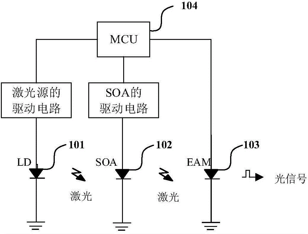
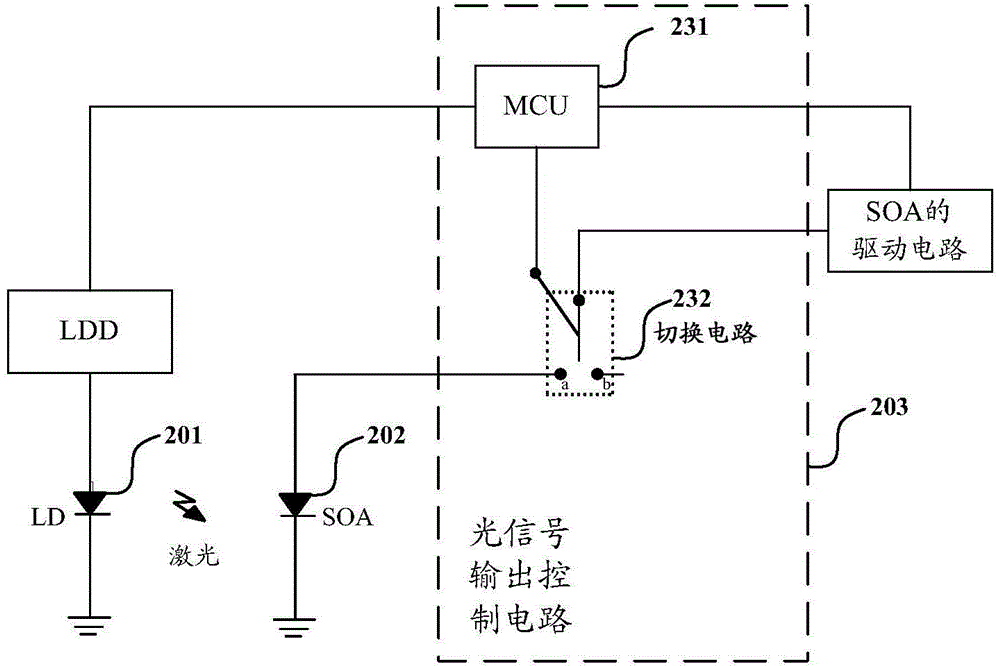
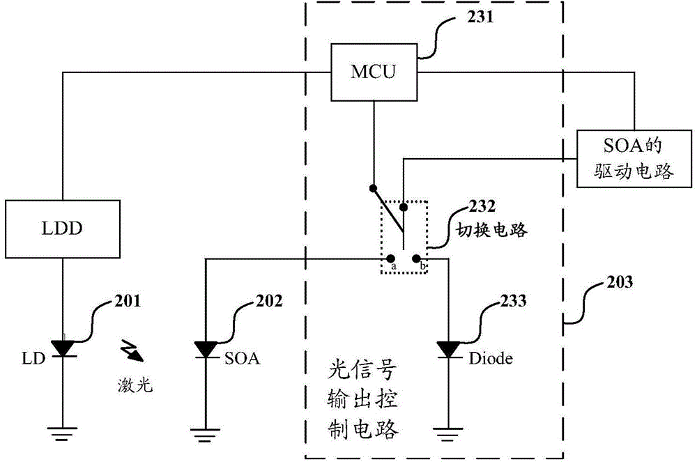
Embodiments of the invention provide an optical module and an optical signal output control method. The optical module comprises a laser source, a semiconductor laser amplifier, and a drive circuit of the semiconductor laser amplifier. The optical module further comprises a switching circuit of which one end is connected with the bias current output end of the drive circuit of the semiconductor laser amplifier, and a controller which is used for making the switching circuit connect the bias current output end of the drive circuit to the semiconductor laser amplifier after receiving an optical signal transmission instruction, and making the switching circuit disconnect the bias current output end of the drive circuit from the semiconductor laser amplifier after receiving an optical signal stop instruction. According to the technical scheme of the invention, the on time and off time of optical signal output of the optical module can be shortened greatly, and quick start and cutoff of optical signal output of the optical module is realized.

Description

technical field [0001] The present invention relates to the technical field of optical communication, in particular, the present invention relates to an optical module and an optical signal output control method. Background technique [0002] Currently, a Passive Optical Network (PON) has been widely deployed as an optical access system. PON usually includes: an optical line terminal OLT (Optical Line Terminal) set at the central office, an optical network unit ONU (Optical Network Unit) set at the terminal, and an ODN (Optical Distribution Network, optical distribution network) connected between the OLT and the ONU. network). The OLT is usually provided with several optical modules, and the optical modules in the OLT are connected to the ODN through optical fibers for transmitting downlink optical signals or receiving uplink optical signals. An optical module is generally arranged in the ONU, and the optical module in the ONU is connected to the ODN through an optical fib...

Claims


Application Information

Patent Timeline
Patent Type & Authority Applications(China)
IPC IPC(8): H04B10/2507H04B10/29H04B10/564
Inventor 杨世海张强赵其圣
Owner HISENSE BROADBAND MULTIMEDIA TECH
Why Eureka
Try Eureka