Electrical control cabinet with heat dissipation protective device at top part

A technology of electrical control cabinets and protective devices, which is applied in the direction of electrical equipment casings/cabinets/drawers, electrical components, electrical equipment structural parts, etc., and can solve problems such as affecting the performance of electrical components, malfunctioning, and large dust in the cabinet. Achieve the effect of solid control cabinet body, increased service life and good heat dissipation effect

Inactive Publication Date: 2016-12-21
江苏明强电气有限公司
View PDF6 Cites 9 Cited by
  • Summary
  • Abstract
  • Description
  • Claims
  • Application Information

AI Technical Summary

Problems solved by technology

[0002] The electrical control cabinet is mainly used for electrical operation and control of the mechanical equipment on site. There are many cables and electrical components installed inside the electrical control cabinet. Especially in recent years, with the advancement of science and technology, high-end precision electrical components have been widely used. Such as precision circuit breakers, frequency converters, PLC modules, relays, thermal stages, transformers, industrial computers, etc., these electrical components tend to generate heat during live work, resulting in excessive heat in the cabinet, affecting the performance of electrical components, and even Cause d...

Method used


Image

  • Electrical control cabinet with heat dissipation protective device at top part
  • Electrical control cabinet with heat dissipation protective device at top part
  • Electrical control cabinet with heat dissipation protective device at top part

Examples


Embodiment Construction

[0015] The following will clearly and completely describe the technical solutions in the embodiments of the present invention with reference to the accompanying drawings in the embodiments of the present invention. Obviously, the described embodiments are only some, not all, embodiments of the present invention. Based on the embodiments of the present invention, all other embodiments obtained by persons of ordinary skill in the art without making creative efforts belong to the protection scope of the present invention.

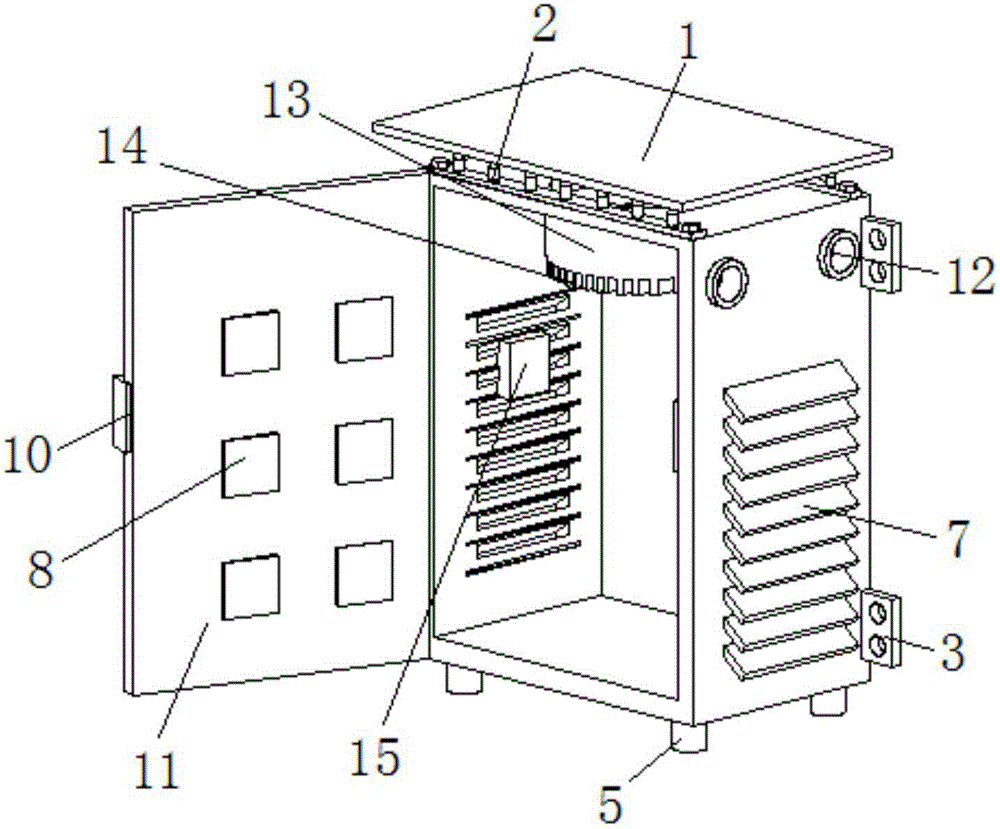
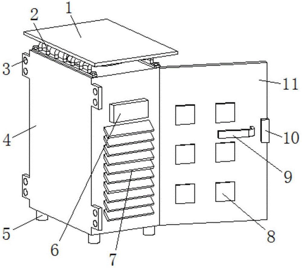
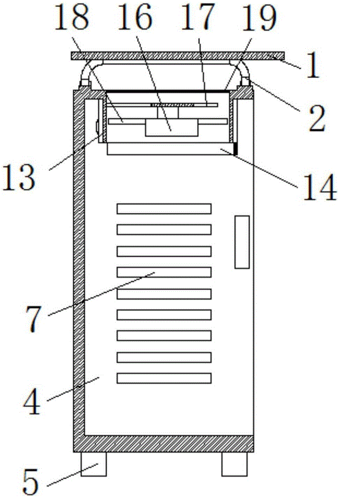
[0016] see Figure 1-3 , the present invention provides a technical solution: an electrical control cabinet with a heat dissipation protection device on the top, including a control cabinet body 4, an opening is provided on the front surface of the control cabinet body 4, and a cabinet door 11 is provided on one side of the opening. The cabinet door 11 makes it more convenient to overhaul the control cabinet. The cabinet door 11 is connected to the control cab...


PUM


Abstract

The invention discloses an electrical control cabinet provided with a heat dissipation protective device at the top part. The electrical control cabinet comprises a control cabinet body, wherein an opening is formed in the front surface of the control cabinet body, one side of the opening is provided with a cabinet door, the cabinet door is connected with the control cabinet body through a hinge, one side of the cabinet door is provided with a lock catch, fan blades are driven to rotate by power, the heat of the electrical control cabinet is dissipated through the rotation of the fan blade, so that the electrical control cabinet has better heat dissipation effect, the lower end of a ventilation pipe is provided with a heat dissipation frame, the heat of the electrical control cabinet is dissipated more quickly by means of the heat dissipation frame, and the control cabinet body is protected by a protective plate and a protective frame, so that the control cabinet body is more solid. The electrical control cabinet provided with the heat dissipation protective device at the top part is simple in structure, can dissipate the heat inside the electrical control cabinet quickly, and can prevent tiny debris particles and a lot of dust from falling into the cabinet from the top part, thereby protecting the electrical appliance elements inside the electrical control cabinet and prolonging the service life of the electrical appliance elements.

Description

technical field [0001] The invention relates to the technical field of electrical control cabinets, in particular to an electrical control cabinet with a heat dissipation protection device on the top. Background technique [0002] The electrical control cabinet is mainly used for electrical operation and control of the mechanical equipment on site. There are many cables and electrical components installed inside the electrical control cabinet. Especially in recent years, with the advancement of science and technology, high-end precision electrical components have been widely used. Such as precision circuit breakers, frequency converters, PLC modules, relays, thermal stages, transformers, industrial computers, etc., these electrical components tend to generate heat during live work, resulting in excessive heat in the cabinet, affecting the performance of electrical components, and even Cause damage to electrical components, cause the electrical control cabinet to fail to work...

Claims


Application Information

Patent Timeline
IPC IPC(8): H05K5/02H05K7/20
CPCH05K5/0213H05K5/0217H05K7/20145H05K7/20172H05K7/20181H05K5/03
Inventor 何明朱新春张云韩燕王文峰
Owner 江苏明强电气有限公司
Why Eureka
Try Eureka