Method and apparatus for indicating d2d resource pool in wireless communication system

A technology of structural units and valve trains, applied in the direction of engine components, machines/engines, mechanical equipment, etc., which can solve problems such as the problem of continuous clamping of connecting clips

Inactive Publication Date: 2016-12-21
SCHAEFFLER TECH AG & CO KG
View PDF9 Cites 2 Cited by
  • Summary
  • Abstract
  • Description
  • Claims
  • Application Information

AI Technical Summary

Problems solved by technology

At the same time, the constant tightening of the connection clips proved problematic

Method used


Image

  • Method and apparatus for indicating d2d resource pool in wireless communication system
  • Method and apparatus for indicating d2d resource pool in wireless communication system
  • Method and apparatus for indicating d2d resource pool in wireless communication system

Examples


Embodiment Construction

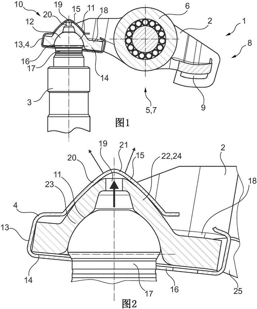
[0018] figure 1 A structural unit 1 of a valve train of an internal combustion engine is disclosed. The structural unit 1 comprises a rocker arm 2 made of thin-walled steel sheet, a support element 3 and a connecting clip 4 made of spring sheet.

[0019] The rocker arm 2 is U-shaped in cross section. The rocker arm has in its central region 5 a cutout 25 with a cam strike surface 6 present as a roller. On its underside 7 , the rocker arm 2 has, on the one hand, a stop 9 for the air exchange valve in the first end 8 and, on the other hand, a ball-and-socket-shaped recess 11 on the second end 10 .

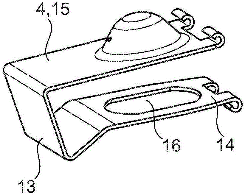
[0020] For example in figure 1 , figure 2 It can be seen that the head 12 of the support element 3 is placed in the last-mentioned recess 11 . The rocker arm 2 is fastened in this case to the head 12 of the support element 3 in an articulated and slip-proof manner via the connecting clip 4 .

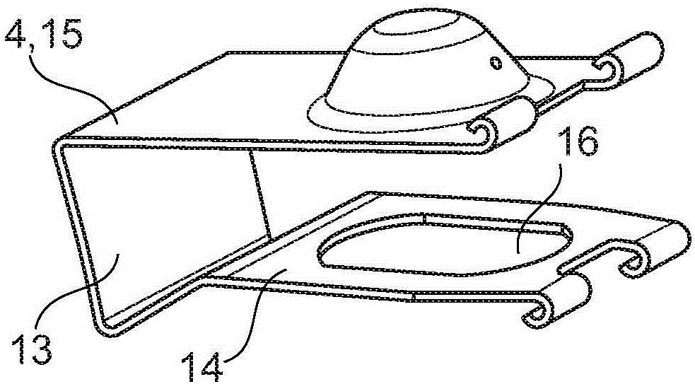
[0021] The connecting clip 4 is implemented in the design of an American foldback cl...


PUM


Abstract

A connection clip (4) fixes a dome-shaped recess located at the end of a drag lever on a head (12) of a support element (3). The connection clip consists of two spring limbs (14, 15) which are connected at one end by a transverse bracket (13). One spring limb (14) rests on the lower face (7) of the drag lever (2), and a recess (16) of said spring limb engages around a retaining region (17) of the support element (3) below the support element head (13). The other spring limb (15) runs on an upper face (18) of the drag lever (2). A channel (19) which is provided by the support element (3) leads through the recess (11) for an injection oil lubrication. The other spring limb (15) of the connection clip (4) lies on the upper face (18) of the drag lever (2) over the dome-shaped recess (11) in a closed manner and has an injection oil bore (20) which is fluidically connected to the channel (19) and which faces away from the drag lever (2) via the second end (10) thereof.

Description

technical field [0001] The invention relates to a structural unit of a valve train of an internal combustion engine, which has a rocker arm, a support element, and a connecting clip, the rocker arm has a cam strike surface in the central region, and the rocker arm has on its lower side a first end for The stop of the air exchange valve and on the second end has a ball-and-socket-shaped recess, via which the rocker arm is connected by a connection of two spring arms connected at one end by a cross bar The clip is hingedly attached to the head of the support element, wherein one spring arm rests on the underside of the rocker arm and encloses the holding area of ​​the support element under its head with a cutout, and another The spring arm extends on the upper side of the rocker arm, and wherein a channel fed by the support element leads through the inner recess for oil injection lubrication. Background technique [0002] Structural units provided with connecting clips are kn...

Claims


Application Information

Patent Timeline
Patent Type & Authority Applications(China)
IPC IPC(8): F01L1/18F01L1/24
CPCF01L1/185F01L1/2405F01L2001/187F01L2810/02F01L1/18
Inventor 彼得·赛勒奥利弗·施内尔
Owner SCHAEFFLER TECH AG & CO KG
Why Eureka
Try Eureka