
Jetting mechanism

A spray mechanism and piston technology, applied to spray devices, single handheld devices, etc., can solve problems such as inconvenient operation of spray guns, increase in valve body volume, and increase in weight of spray guns, and achieve large spray dose, long range, and effective surface. wide effect

Active Publication Date: 2017-01-04
北京北机机电工业有限责任公司
View PDF10 Cites 4 Cited by
  • Summary
  • Abstract
  • Description
  • Claims
  • Application Information

AI Technical Summary

Problems solved by technology

Restricted by the structure of the valve body, in order to increase the shooting range, it is necessary to increase the diameter of the flow channel and the volume of the valve body, which will increase the overall weight of the spray gun and make the operation of the spray gun inconvenient

Method used


Image

  • Jetting mechanism

Examples


Embodiment Construction

[0017] The present invention will be described in detail below with reference to the accompanying drawings and examples.

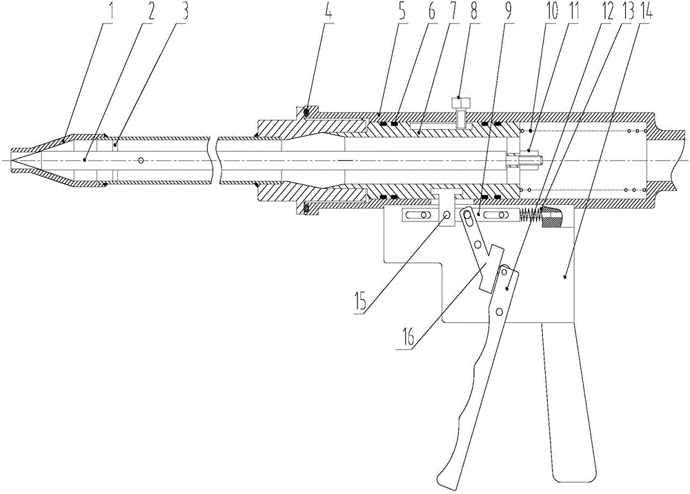
[0018] The invention provides a spraying mechanism, see attached figure 1 , including: gun barrel welding 1, valve stem 2, guide rod 3, first sealing ring 4, valve seat 5, second sealing ring 6, piston 7, guide pin 8, first connecting rod 9, return spring 10, Nut 11, trigger 12, connecting rod return spring 13, box body 14, pushing block 15 and second connecting rod 16;

[0019] The gun barrel welding 1 is composed of a conical barrel section and a small cylindrical section and a large cylindrical section respectively docked with the two ends of the conical cylindrical section; pad;

[0020] One end of the valve stem 2 is a conical structure;

[0021] The outer circumferential surface of the piston 7 is processed with strip grooves;

[0022] The outer peripheral surface of the valve seat 5 is processed with a strip-shaped through hole;

[0023] The ov...


PUM


Abstract

The invention discloses a jetting mechanism and belongs to the technical field of jetting. The jetting mechanism comprises a gun-barrel welding device, a valve rod, a valve seat, a piston, a first connecting rod, a reset spring, a trigger, a connecting rod reset spring, a case body, a push block and a second connecting rod. A large barrel section of the gun-barrel welding device abuts against the valve seat; the piston is mounted on the inner circumferential face of the valve seat in a sleeved manner; the rest spring is mounted inside the valve seat, and the valve rod is mounted in a cavity formed by the gun-barrel welding device and the piston; the case body is fixed to the outer circumferential face of the valve seat; the first connecting rod is mounted on the case body and moves in the direction in parallel with the axis of the valve rod; one end of the connecting rod reset spring is fixed to the case body, and the other end of the connecting rod reset spring abuts against the end face of the first connecting rod; one end of the push block is fixed to the first connecting rod, and after penetrating a strip-shaped through hole in the valve seat, the other end of the push block is fixed to the piston; and the trigger is mounted on the case body and is connected with the first connecting rod through the second connecting rod. By means of the jetting mechanism, a jetting medium in the cavity of the mechanism can be controlled to be jetted out through a mechanical structure.

Description

technical field [0001] The invention belongs to the technical field of spraying, and in particular relates to a spraying mechanism. Background technique [0002] The existing injection technology is mainly used for atomization and short-distance injection. The portable spray gun mechanism is a kind of injection technology. The control mechanism in the form of a ball valve or a needle valve is mostly used in the market. The valve body has a small caliber, a small medium flow rate, and a short range. Restricted by the structure of the valve body, to increase the shooting range, it is necessary to increase the aperture of the flow channel and the volume of the valve body, which will lead to an increase in the overall weight of the spray gun and make the operation of the spray gun inconvenient. Contents of the invention [0003] In view of this, the object of the present invention is to provide an injection mechanism, which can control the injection of the injection medium in...

Claims


Application Information

Patent Timeline
Patent Type & Authority Applications(China)
IPC IPC(8): B05B11/02
CPCB05B11/02
Inventor 李振兴陈伟毛俊中赵哲张来张赫
Owner 北京北机机电工业有限责任公司
Learn More